4G/5G Base Station

Wireless Excellence Limited
Application Note: 4G & 5G Handover
05 August 2021
1 Introduction
This application note aims to provide the procedure for running intra and Inter eNB/gNB handover scenarios on CableFree products using a commercial UE.
Please note this application note refers to lab systems with radio front ends. For applications using Remote Radio Heads (RRH) with CPRI interfaces there may be small configuration differences.
2 Handover Intra-eNB
2.1 LTE Network architecture

Lab test setup is composed of :
- One MME and one eNB running on same PC and connected through S1 interface.
- One or two radio front ends.
2.2 Constraints
In order to test Inter Frequency/Band handover between two cells running on same eNB, one or two radio front ends are required depending on the spectrum used by both cells.
PCIe radio front ends have a bandwidth of 56Mhz. By consequence, if both cells can fit in this bandwidth, handover can be carried out with one SDR only. Otherwise, two radio front ends are required.

In the example above, there is no overlap between the two cells neither in uplink nor in downlink. If a higher bandwidth had been used (20Mhz for instance), both cells would have overlapped, resulting in interference.
Other constraints:
• The difference of the centre frequencies of each cell must be a multiple of 300 kHz (hence the difference of their EARFCN must be a multiple of 3).
• The difference between the centre frequency of each cell and the average of centre frequencies must be a multiple of 15 kHz.
• The number of cells that could be configured in a frequency band depends on the total bandwidth of the lte band and the configured bandwidth of each cell + the offsets.
• The cells must have the same prach-ConfigIndex (SIB2), i.e. their PRACH must have the same duration and transmitted in the same subframes.
• Multiple cells can be set at the same frequency provided their physical cell identity (n_ id_cell property) and PRACH rootSequenceIndex (SIB2) are different to minimise the inter-cell interference. In the current version, there is no resource reservation among the cells, so a performance degradation happens if they transmit at the same time in the same resource blocks. So it is currently better to use cells at different frequencies.
Let’s take the following example to configure 3 cells in band 7:
cell 1 DL frequency: 2627 MHz
cell 2 DL frequency: 2642 MHz
cell 3 DL frequency: 2657 MHz
average_dl_freq = (2627 + 2642 + 2657)/3 = 2642 MHz cell1_freq_offset = 2627 − 2642 = −15 MHz
cell2_freq_offset = 2642 − 2642 = 0 MHz
cell3_freq_offset = 2657 − 2642 = 15 MHz
We can observe that the difference between the centre frequency of each cell and the average of centre frequencies is indeed a multiple of 15 kHz and the difference between the DL EARFCNs are a multiple of 3.
2.3 MME configuration
For running intra eNB Handover, no specific configuration is required on MME side. Default configuration files can be used without customisation
2.4 eNB configuration with both cells running on the same radio front end
As described in previous section, it’s possible to configure two or more cells on the same radio front end as long as it fulfills the spectrum constraints. See [constraints], page 2, for more details.
2.4.1 Neighbour cell info
In enb.cfg file, for each cell, set neighbour cell info using ncell_list parameters:
/* high 24 bits of SIB1.cellIdentifier */ enb_id: 0x1A2E0,
cell_list: [
{
dl_earfcn: 3350, /* DL centre frequency: 2680 MHz (Band 7) */
n_id_cell: 1, cell_id: 0x01, tac: 0x0001,
root_sequence_index: 204, /* PRACH root sequence index */
/* Neighbour cell list (used for handover) */ ncell_list: [
{ n_id_cell: 2, dl_earfcn: 3299, cell_id: 0x1a2e002, tac: 1 },
],
},
{
dl_earfcn: 3299, /* DL centre frequency: 2674.9 MHz (Band 7) */
n_id_cell: 2, cell_id: 0x02, tac: 0x0001,
root_sequence_index: 86, /* PRACH root sequence index */
/* Neighbour cell list (used for handover) */ ncell_list: [
{ n_id_cell: 1, dl_earfcn: 3350, cell_id: 0x1a2e001, tac: 1 },
],
},
], /* cell_list */
where:
- n_id_cell is n id cell of neighbour cell
- dl_earfcn is the downlink earfcn of neighbour cell
- cell_id is the EUTRAN cell identifier (concatenation of the enb_id and cell_id of neighbour cell)
Please refer to “lteenb” eNodeB/gNodeB manual for more details about cell list parameters.
2.4.2 Measurement configuration
In order to trigger measurement reports (a1,a2 and a3) at UE side when cells level will fluctuate, set meas_config_desc parameters in enb.cfg file (under cell_default object):
Example:
/* measurement configuration */ meas_config_desc: {
a1_report_type: “rsrp”, a1_rsrp: -70,
a1_hysteresis: 0,
a1_time_to_trigger: 640, a2_report_type: “rsrp”, a2_rsrp: -80,
a2_hysteresis: 0,
a2_time_to_trigger: 640, a3_report_type: “rsrp”,
a3_hysteresis: 0,
a3_time_to_trigger: 480,
},
/* measurement gap configuration */ meas_gap_config: “gp0”,
/* if true, initiate a handover when a suitable measurement report is received */
ho_from_meas: true,
Please refer to “lteenb” eNodeB/gNodeB manual for more details about meas config desc parameters.
2.5 eNB configuration with cells running on two radio front ends
For Inter frequency/band handover two radio front ends may be required if spectrum used by both cells is larger than SDR bandwidth (56Mhz for PCIe radio front end).
In that case, cell configuration is slightly different and rf_port used by each cell must be defined. Others parameters (Neighbour cell info and Measurement configuration) remain identical.
Example:
cell_list: [
{
rf_port: 0, /* means that cell 0x01 will use dev0=/dev/sdr0 */ dl_earfcn: 3350, /* DL centre frequency: 2680 MHz (Band 7) */ n_id_cell: 1,
cell_id: 0x01, tac: 0x0001,
root_sequence_index: 204, /* PRACH root sequence index */
/* Neighbour cell list (used for handover) */ ncell_list: [
{ n_id_cell: 2, dl_earfcn: 3299, cell_id: 0x1a2e002, tac: 1 },
],
},
{
rf_port: 1, /* means that cell 0x02 will use dev1=/dev/sdr1 */ dl_earfcn: 3299, /* DL centre frequency: 2674.9 MHz (Band 7) */ n_id_cell: 2,
cell_id: 0x02, tac: 0x0001,
root_sequence_index: 86, /* PRACH root sequence index */
/* Neighbour cell list (used for handover) */ ncell_list: [
{ n_id_cell: 1, dl_earfcn: 3350, cell_id: 0x1a2e001, tac: 1 },
],
In config/rf driver, both radio front ends must be defined as well. See trx sdr.pdf for more details.
rf_driver: {
name: “sdr”,
/* list of devices. ’dev0’ is always the master. */ args: “dev0=/dev/sdr0,dev1=/dev/sdr1”,
Note: When two radio front ends are used on same eNB, SDR1 must be connected to SDR0 through USB cable provided by CableFree in order to synchronise the Radio frames. See in- stallguide.pdf for more details.
2.6 Handover triggered by UE measurement report
In order to carry out handover based on UE measurement report, once enb is configured, the only thing to do is to decrease step by step cell gain at eNB side (command cell_gain cell_id gain on eNB screen). Example : cell gain 1 -20
Note: To perform handover and not a reselection, it’s recommended to run uplink or downlink transfer using iperf as instance in order to keep UE in RRC connected state.
2.7 Blind handover triggered by eNB
In order to carry out blind handover, eNB command can be used. To do this:
- Start downlink or Uplink transfer (with iperf as instance) in order to keep UE in RRC connected state
- On eNB screen, enter ue command to identify UE id at eNB level (eNB_UE_ID)
- Enter handover command with the following parameters : eNB UE ID pci dl earfcn type
- Where :eNB UE ID is UE ID at eNB level
- pci is physical Cell ID of target cell (neighbour cell).
- dl_earfcn is downlink earfcn of target cell (neighbour cell).
- type is handover type. Use intra here.
Example of handover command : handover 14 2 3299 intra
3 Handover inter-eNB
3.1 Prerequisites
In order to test handover between two different eNB, some prerequisites must be fulfilled:
• Each eNB must be running on a different BBU/x86 (host). It’s not possible to run 2 eNB components on the same hardware.
• By consequence two eNB licenses are required to run inter eNB handover scenario. Only one MME license is needed.
• Radio frames must be synchronised between eNB1 and eNB2.
The most convenient way is to use GPS antenna on both eNB. Any active GPS antenna accepting a 3.3V DC supply can be used.
• Each eNB is configured with one cell (using one radio front end). UE can attach on each cell independently.
Note: MME component can be run on same PC as eNB. This will be the setup described in this document.
3.2 LTE Network architecture

Setup is composed of :
- One MME and one eNB (named eNB1) running on the same PC (IP address 192.168.30.1)
- A second eNB (eNB2) running on a different PC (IP address 192.168.30.2)
MME and both eNB connected through S1 interface eNB1 and eNB2 connected through X2 interface.
3.3 MME configuration
In order to connect both eNB to same MME, default (loopback) GTP address must be changed and replaced with IP address of PC where MME component is running.
in mme.cfg file, change : gtp_addr: “127.0.1.100”, with
gtp_addr: “192.168.30.1”,
Note: If another MME component is running on PC where eNB2 is running, this one must be turned off.
3.4 eNB1 configuration
This section aims to describe the modifications required on eNB to carry out inter eNB handover. The initial setting of eNB (cell, earfcn , gain, SDR configuration, etc.. ) are not covered in this document.
Please refer to lteots.pdf document for more details on basic configurations.
3.4.1 MME address
In enb.cfg file, replace default (loopback) MME address with IP address of PC1 (192.168.30.1).
mme_list: [
{
/* address of MME for S1AP connection. Must be modified if the MME runs on a different host. */
mme_addr: “192.168.30.1”,
},
],
3.4.2 GTP address
As for MME, default GTP address must be changed and replaced with IP address of the PC1 (instead of using loopback IP address).
However, as IP address of PC1 is already used by MME, it’s not possible to reuse it.
The solution is to create an IP alias (192.168.30.3 as instance) and use this alias as gtp addr for eNB1.
To create the alias:
- Run ifconfig command
- Check ethernet interface name (example “eth2:” )
- Enter command ifconfig eth2:1 192.168.30.3/24
- Check alias has been created with ifconfig command
Note: This hint is not needed if MME is running on its own PC and don’t have, as consequence, the same IP address as eNB1.
Once the IP alias has been created , update enb.cfg file and replace default gtp addr with this value.
/* GTP bind address (=address of the ethernet interface connected to the MME). Must be modified if the MME runs on a different host. */
gtp_addr: “192.168.30.3”,
3.4.3 X2 address
In order to connect both eNB through X2 interface, X2 peer IP address (eNB2) must be set. In enb.cfg file , add the following parameter :
x2_peers:[“192.168.30.2”],
3.4.4 eNB ID
Each eNB must have a unique ID. The default value is:
enb_id: 0x1A2D0
3.4.5 Neighbour cell info
In enb.cfg file, set neighbour cell (eNB2 cell) info using ncell_list parameters:
cell_list: [
{
dl_earfcn: 3350, /* DL centre frequency: 2680 MHz (Band 7) */
n_id_cell: 1, cell_id: 0x01, tac: 0x0001,
root_sequence_index: 204, /* PRACH root sequence index */
/* Neighbour cell list (used for handover) */ ncell_list: [
{ n_id_cell: 2, dl_earfcn: 6300, cell_id: 0x1A2D102, tac: 1 },
],
},
Where:
- n_id_cell is n id cell of eNB2 cell
- dl_earfcn is the downlink earfcn of eNB2 cell
- cell_id is the EUTRAN cell identifier (concatenation of the enb_id and cell_id of eNB2 cell)
3.4.6 Measurement configuration
In order to trigger measurement reports (a1,a2 and a3) at UE side when cells level will fluctuate, set meas_config_desc parameters in enb.cfg file (under cell_default object) : Example:
/* measurement configuration */ meas_config_desc: {
a1_report_type: “rsrp”, a1_rsrp: -70,
a1_hysteresis: 0,
a1_time_to_trigger: 640, a2_report_type: “rsrp”,
a2_hysteresis: 0,
a2_time_to_trigger: 640, a3_report_type: “rsrp”, a3_offset: 6,
a3_hysteresis: 0,
a3_time_to_trigger: 480,
},
/* measurement gap configuration */ meas_gap_config: “gp0”,
/* if true, initiate a handover when a suitable measurement report is received */
ho_from_meas: true,
Please refer to “lteenb” eNodeB/gNodeB manual for more details about meas config desc parameters
3.4.7 SDR clock setting
As described in hardware prerequisite section, both eNB must be synchronised using a GPS clock antenna.
If PCIe radio front ends are used on your setup, the synchronization source must be changed.
In /root/enb/config/rf driver folder, open config file used by enb.cfg file and uncomment
sync parameter.
/* synchronization source: internal, gps, external (default = internal) */ sync: “gps”,
Whith this modification, PCIe radio front end will get its clock from the GPS antenna.
3.5 eNB2 configuration
3.5.1 MME address
As for eNB1 , in enb.cfg file, replace default (loopback) MME address with IP address of PC where MME component is running (192.168.30.1).
mme_list: [
{
/* address of MME for S1AP connection. Must be modified if the MME runs on a different host. */
mme_addr: “192.168.30.1”,
},
],
3.5.2 eNB ID
As both eNB are connected to same MME component, their ID must be different. In enb.cfg file change enb id to be different of eNB1
/* high 24 bits of SIB1.cellIdentifier */ enb_id: 0x1A2D1,
3.5.3 GTP address
As for eNB1 , GTP address must be changed.
However, as there is no MME component on this PC (eNB2 only), the IP constraint encountered with eNB1 is not present and GTP address can be the one of PC2.
/* GTP bind address (=address of the ethernet interface connected to the MME). Must be modified if the MME runs on a different host. */
gtp_addr: “192.168.30.2”,
3.5.4 X2 address
As for eNB1, X2 peer IP address (eNB1) must be set. In enb.cfg file, add the following parameter:
x2_peers:[“192.168.30.1”],
3.5.5 Neighbour cell info
As for eNB1, in enb.cfg file, set neighbour cell (eNB1 cell) info using ncell_list parameters:
cell_list: [
{
dl_earfcn: 6300, /* DL centre frequency: 2680 MHz (Band 7) */
n_id_cell: 2, cell_id: 0x01, tac: 0x0001,
root_sequence_index: 204, /* PRACH root sequence index */
/* Neighbour cell list (used for handover) */ ncell_list: [
{ n_id_cell: 1, dl_earfcn: 3350, cell_id: 0x1A2D001, tac: 1 },
],
},
where:
- n_id_cell is n id cell of eNB1 cell
- dl_earfcn is the downlink earfcn of eNB1 cell
- cell_id is the EUTRAN cell identifier (concatenation of the enb_id and cell_id of eNB1 cell),
3.5.6 Measurement configuration
As for eNB1 , in enb.cfg file, under cell default object, set meas_config_desc parameters: Example :
/* measurement configuration */ meas_config_desc: {
a1_report_type: “rsrp”, a1_rsrp: -70,
a1_hysteresis: 0,
a1_time_to_trigger: 640, a2_report_type: “rsrp”, a2_rsrp: -80,
a2_time_to_trigger: 640, a3_report_type: “rsrp”, a3_offset: 6,
a3_hysteresis: 0,
a3_time_to_trigger: 480,
},
/* measurement gap configuration */ meas_gap_config: “gp0”,
/* if true, initiate a handover when a suitable measurement report is received */
ho_from_meas: true,
Please refer to “lteenb” eNodeB/gNodeB manual for more details about meas config desc parameters.
3.6 GPS antenna connection
3.6.1 Connection
- Place your GPS antenna in a place where GPS signal is likely to be found (outdoors).
- Connect each GPS antenna to SMA connector GPS of PCIe radio front end on eNB1 and eNB2.
3.6.2 GPS test
Once connection is done, you can check if GPS clock is locked. To do this :
- Stop LTE service on your PC (service lte stop)
- Go under /root/trx_sdr folder
- Enter the command ./sdr_util -c 0 gps_state
- If GPS clock is locked, date and time will be displayed :
GPS locked
TAI: 2018-11-20 16:18:29
UTC: 2018-11-20 16:17:52
Note: The GPS takes a few minutes to lock if the GPS antenna is connected.
3.7 S1 and X2 connection check
Once eNB1,eNB2 and MME have be configured, you can start each component and check the connections.
- On MME screen, enter enb command. Both eNB should be listed
- On both eNB screen, enter s1 command. S1 connection state should be “setup done”
- On both eNB screen, enter x2 command. X2 Peer connection state should be “setup done”
- If X2 peer connection state is “disconnected”, just enter x2connect command and check again with x2 command afterwards.
Your setup is now completed! You can connect your UE and run handover test .
3.8 S1/X2 Handover triggered by UE measurement report
In order to carry out Handover based on UE measurement report, the only thing to is to decrease step by step cell gain at eNB side (command cell_gain cell_id gain on eNB screen).
Example : cell gain 1 -20
To trigger a S1 handover rather than X2, just remove the x2 peers connection in eNB configu- ration files.
Note: To perform Handover and not a reselection, it’s recommended to run uplink or downlink transfer with iperf as instance in order to keep UE in RRC connected state.
3.9 Blind S1/X2 Handover triggered by eNB
In order to carry out blind X2 or S1 handover, eNB command can be used. To do this:
- Start downlink or Uplink transfer (with iperf as instance) in order to keep UE in RRC connected state
- On eNB screen, enter ue command to identify UE id at eNB level (eNB_UE_ID)
- Enter handover command with the following parameters : eNB UE ID pci dl earfcn type Where :eNB UE ID is UE ID at eNB levelpci is physical Cell ID of target cell (eNB2).dl earfcn is downlink earfcn of target cell (eNB2).
- type is handover type. Can be intra, s1 or x2.
Example of X2 handover command : handover 14 2 3350 x2
4 Handover using UE simulator
4.1 Hardware prerequisite
When a UE simulator is used for testing handover, two radio front ends are required. SDR1 card will be connected to cell 1, SDR2 card will be connected to cell 2.
4.2 UE configuration file
In ue.cfg file, both cells must be declared. Example :
cells: [
{
dl_earfcn: 6300,
n_antenna_dl: 2,
n_antenna_ul: 1,
},
{
dl_earfcn: 3350,
n_antenna_dl: 2,
n_antenna_ul: 1,
},
],
On top of that, SDR mapping must be defined : Example :
rf_driver: {
name: “sdr”,
args: “dev0=/dev/sdr0,dev1=/dev/sdr1”,
},
The mapping between Cells and radio front ends is made automatically and follows the same order as the declaration in the configuration file.
The example here above results in:
- Radio front end #0 listening on earfcn 6300
- Radio front end #1 listening on earfcn 3350
The RF connection must be done accordingly.
For 5G SA handover similar concepts apply, for that please refer to the provided example configuration file ue-nr-2cc-sa.cfg.
Note: When two cells are declared on UE side, both cells must be active otherwise UE will remain in SIB detection state indefinitely.
5 Handover call flow
In order to help the investigation, here are the expected call flows of handover scenario.
5.1 X2 Handover triggered by UE measurement


1. RRC Connection Reconfiguration:
Sent by eNB to UE to configure measurement report events.
Three event reports a1, a2, a3 are configured in RRC Connection Reconfiguration.
Two event reports a2, a3 are activated.
Example of a1 report configuration within RRC Connection Reconfiguration message:
reportConfigToAddModList {
{
reportConfigId 1,
reportConfig reportConfigEUTRA: { triggerType event: {
eventId eventA1: {
a1-Threshold threshold-RSRP: 90
},
hysteresis 0, timeToTrigger ms640
},
triggerQuantity rsrp, reportQuantity both, maxReportCells 1, reportInterval ms120, reportAmount r1
}
2. Measurement Report A2:
Sent by UE to eNB when the serving cell becomes worse than a threshold.
message c1: measurementReport: { criticalExtensions c1: measurementReport-r8: {
measResults { measId 2, measResultPCell {
rsrpResult 79,
rsrqResult 34
}
}
3. RRC Connection Reconfiguration:
Upon reception of a2 meas report, network reconfigures UE event report (deactivate a2, activate a1 and activate Measurement Gap) through RRC Connection Reconfiguration message.
Note: Measurement Gap have an impact on throughput as no transmission and reception happens during gap periods.

4. Measurement Report A3:
Sent by UE to eNB when a neighbouring cell becomes better than the serving cell by an offset.
Upon reception of a3 meas report, network trigger the Handover through X2 interface.
message c1: measurementReport: { criticalExtensions c1: measurementReport-r8: {
measResults { measId 3, measResultPCell {
rsrpResult 79,
rsrqResult 34
},
measResultNeighCells measResultListEUTRA: {
{
physCellId 2, measResult {
rsrpResult 90,
rsrqResult 34
}
5. Handover request:
Sent by eNB1 to eNB2 to set up the inter eNB handover through X2AP interface (X2AP trace level must be set to “debug” to see this message).
6. Handover request acknowledge:
Sent by eNB2 to eNB1 to acknowledge eNB handover.
7. RRC Connection Reconfiguration:
Once eNB2 acknowledges the X2 handover request, eNB1 triggers a handover at UE side by sending the RRCconnectionReconfiguration.
This message provides mobility information as described below as well as target cell information for UE to establish a RRC connection request on target cell.
mobilityControlInfo {
targetPhysCellId 2, carrierFreq {
dl-CarrierFreq 3350
},
8. RRC Connection Reconfiguration Complete:
Once UE has moved from eNB1 to eNB2 , it sends the RCC Connection Reconfiguration Complete on the target cell (eNB2).
To see this message, a log must be captured on eNB2 this time Traffic should be now resumed on target cell.
5.2 S1 Handover triggered by UE measurement
S1 inter eNB handover has the same call flow as X2 handover when it comes to the messages exchanged between UE and eNB (See [X2 handover], page 15, call flow for more details).
The main difference is on the Handover procedure at eNB side. Handover request is sent to MME through S1 interface and not to peer eNB through X2 interface.


1. Handover required:
Upon reception of Measurement Report A3, eNB1 triggers a Handover by sending a Handover required to MME. The source eNodeB indicates which bearers are subject to data forwarding.
2. Handover Request:
MME sends Handover Request message to the target eNodeB. This message creates the UE context in the target eNodeB, including information about the bearers, and the security context
3. Handover Request Acknowledge:
Target eNodeB responds back to the MME with a Handover Request Acknowledge message. This message carries the Handover Command message (RRC Connection Reconfiguration Request) in a transparent container.
4. Handover Command:
MME sends a Handover Command message to the source eNodeB.
5. RRC Connection Reconfiguration:
Upon reception of the Handover command, source eNB sends the RRC Connection Reconfiguration message to the UE. The message contains a new C-RNTI and new DRB IDs. Upon reception of this message the UE will remove any EPS bearers for which it did not receive the corresponding EPS radio bearers in the target cell.
6. RRC Connection Reconfiguration Complete:
UE uses the preamble assigned in the handover command to send a RACH to the target eNodeB. The target eNodeB accepts the request and responds back with a timing adjustment and an uplink resource. UE uses the assigned resources to transmit the RRC Connection.
Reconfiguration Complete (Handover Confirm message).
7. Handover Notify:
Target eNodeB sends a Handover Notify message to MME. Handover is successful.
6 5G SA Handover

CableFree software supports intra gNB, XnAP and NGAP Handover.
6.1 Intra-gNB Handover
The gNodeB can run several NR cells. The cells can be configured individually and share the same NG interfaces with the Core Network.
Cells can be configured on one (intra-band) or several (intra/inter band) radio front ends. Refer to “lteenb” eNodeB/gNodeB manual, for limitations related to intra-band cells configured on the same radio front end.
An example of multi cell configuration for SA handover is given in config/gnb-sa-ho.cfg. For each cell, a list of neighbour cells can be provided as in the example below:
ncell_list: [
{
rat: “nr”, cell_id: 0x02,
}
],
where cell_id is the cell id of the neighbour cell.
The handover can be manually initiated with the handover monitor command, the handover remote API, or automatically initiated based on UE measurements.
In case of handover based on UE measurement reports, a measurement object can be configured as in the example below:
/* measurement configuration */ meas_config_desc: {
a1_report_type: “rsrp”, a1_rsrp: -60,
a1_hysteresis: 10,
a1_time_to_trigger: 100, a2_report_type: “rsrp”, a2_rsrp: -70,
a2_hysteresis: 0,
a2_time_to_trigger: 100, a3_report_type: “rsrp”, a3_offset: 6,
a3_hysteresis: 0,
a3_time_to_trigger: 100,
},
meas_gap_config: { pattern_id: 0
},
For handover procedure triggered by UE measurement report refer to [Handover triggered by UE measurement report], page 6.
To perform blind intra gNB handover triggered by gNB, the handover command or remote API can be used, refer to “lteenb” eNodeB/gNodeB manual for more details.
6.2 Inter-gNB Handover
The same prerequisites as per inter-eNB [Prerequisites], page 7, apply.
In case of inter gNB Handover (XnAP or NGAP), each gNB runs on a different host and they are both connected to the same AMF. AMF can run on one of the gNB machine or on a third one. The gtp address defined in each gNB configuration has to be set to the address of the ethernet interface connected to the AMF.
/* GTP bind address (=address of the ethernet interface connected to the AMF). Must be modified if the AMF runs on a different host. */
gtp_addr: “192.168.30.1”,
As both gNBs are connected to same AMF component, their ID must be different. Use a unique gnb id on each configuration file.
gnb_id: 0x12345,
Each gNB configuration must define the serving cell and a list of fully described neighbour cells, as in the example below:
nr_cell_list: [
{
rf_port: 0, cell_id: 0x01, n_id_cell: 500,
band: 78,
dl_nr_arfcn: 621300,
ncell_list: [
{
ssb_nr_arfcn: 525850,
dl_nr_arfcn: 526000,
ul_nr_arfcn: 502000,
n_id_cell: 501,
gnb_id_bits: 28, nr_cell_id: 0x1234502, tac: 1,
band: 7,
ssb_subcarrier_spacing: 15,
ssb_period: 5,
ssb_offset: 0,
ssb_duration: 1
}],
}
Refer to “lteenb” eNodeB/gNodeB manual for more details about each parameter.
6.2.1 XnAP Handover
To perform XnAP handover, a Xn connection between the gNBs is needed, for that xn_peers parameter has to be set to the ip address of the other gNB (refer to “lteenb” eNodeB/gNodeB manual).
xn_peers:[“192.168.30.2”],
If this interface is not connected, NGAP handover is performed.
6.2.2 Handover procedures
The handover can be manually initiated with the handover monitor command, the handover remote API, or automatically initiated based on UE measurements.
In case of handover based on UE measurements, the same measurement configuration as for intra gNB handover can be used on both gNB.
/* measurement configuration */ meas_config_desc: {
a1_report_type: “rsrp”, a1_rsrp: -60,
a1_hysteresis: 10,
a1_time_to_trigger: 100, a2_report_type: “rsrp”, a2_rsrp: -70,
a2_hysteresis: 0,
a2_time_to_trigger: 100, a3_report_type: “rsrp”, a3_offset: 6,
a3_hysteresis: 0,
a3_time_to_trigger: 100,
},
meas_gap_config: { pattern_id: 0
},
To trigger an handover based on UE measurement report refer to [Handover triggered by UE measurement report].
For details about handover monitor and remote API command refer to “lteenb” eNodeB/gNodeB manual.
7 Troubleshooting
This chapter aims to list some basic checks to be done when handover is not carry out as expected.
7.1 Preconditions
Before to start handover testing, you must check first that UE can connect on each eNB/gNB independently and run Uplink/Downlink transfer.
If UE can’t attach, check that:
• For 4G, eNB and MME are connected using s1 command on eNB screen. S1 connection state should be “setup done”
• For 5G, gNB and 5GS are connected using xn command on eNB screen. Xn connection state should be “setup done”
• (For inter eNB/gNB handover) Check GPS clock is locked using ./sdr_util gps_state command under /root/trx sdr folder (LTE service must be turned off previously). If GPS clock is locked, date and time will be displayed.
7.2 Measurement reports not triggered
If measurement reports are not sent by UE, check that :
- Measurement configuration parameters have been set in enb.cfg file
- Thresholds set in Measurement configuration are not too low and that UE doesn’t lose the RRC connection before sending the events. a1 rsrp: -70 and a2 rsrp: -80 can be used as instance.
- UE is in connected mode during the test and not it idle when cell conditions fulfil handover conditions.
7.3 Handover is triggered but UE fails to move on target cell
If after handover, UE is not seen on target cells check that
- Radio frame are synchronised on both cells thanks to GPS antenna clock
- UE can attach previously on target cell
- Cell power of target cell is good enough for UE to handover (may happen when consecutive handover are triggered between two cells)
7.4 TRX discontinuity too wide
This message may happen if both cells running on two different radio front ends of same enB are not synchronised. In that case, check that USB cable is connected between OUT and IN of master and slave radio front end respectively. See installguide.pdf for more details.
For Further Information
Please contact CableFree Support
support@cablefree.net

Wireless Excellence Limited
Application Note: 4G & 5G SIM card Authentication
16 August 2021
Authentication refers to the idea of validating the identity of a user or a device trying to access the resources provided by a given service and Authorisation helps in controlling the access to these resources. In the case of 4G & 5G LTE wireless networks, authentication is used to enable a user device such as a mobile phone or an IoT device to connect to the network and use the resources provided by the network such as calling, Internet/data services or messaging services. Authorisation is used to check if the user connected to the network can actually be granted services. For example:
- Authentication: Check if the user device with the SIM card is actually owned by the network to which it is trying to connect to.
- Authorisation: Check if the user has sufficient credit balance to access the data services at 1 MBps.
How this really happens in LTE Networks:
LTE networks use the Evolved Packet System Authentication and Key Agreement (EPS-AKA) procedure for bidirectionally authenticating the user i.e. authenticating the user to the network and the network to the user.

Breaking this down into the parts that we really need:
Each USIM card produced by the network operator contains a cryptographic key, Ki, which is also known to the network operator and stored in the HSS. To authenticate, this key is used to:
- Have the UE authenticate the network: Why? This is to prove that the UE is indeed speaking to the network to which it is supposed to be talking to in the first place.
- Have the network authenticate the UE: Why? This is to ensure that the UE who has actually paid for the network service and belongs to the network is the one who receives access to it.
Protocol Call Flow for Authentication
Attach Request
In order to join the network, the UE firstly sends an attach request to the MME via the eNB (base station) with the corresponding PLMN Identity, Mobile Country Code (MCC), Mobile Network Code (MNC) and a cell ID. The MME sends a back a response to the UE requesting for an IMSI. This message is known as an Identity Request and is sent as a Downlink NAS Transport message. The uplink NAS message from the UE is an Identity Response which contains the mobile identity (IMSI) value thereby completing the Attach request phase of the protocol.
Authentication Information Request and Response
After receiving the Identity Response, The MME sends a diameter (S6a) message called Authentication Information Request (AIR) from the MME to the HSS and sends the corresponding mobile identity. The HSS on receiving this information computes is responsible for:
- Checking if the subscriber corresponding to the IMSI value is a genuine subscriber belonging to the network.
- Performing the necessary cryptographic operations to generate an authentication vector (AV) necessary to challenge the UE for authentication.
The response from the HSS to the MME i.e. Authentication Information Answer (AIA) contains the authentication information which includes a random byte array denoted by RAND, the expected response from the UE to the MME denoted by XRES, the authentication response denoted by AUTN, and a shared key called the Key Access Security Management Entries denoted by Kasme.
So how are these values generated? Let’s dig deeper into the HSS to see what happens to create this Authentication Information Answer (AIA) response.
Authentication Vector Generation
The HSS contains the LTE key Ki which is the same as the key that’s present on the USIM of the UE. In addition, the SIM card also contains the network operators key OPc and an Authentication Management Field (AMF). These are two very critical secret keys which should be safeguarded by the network operators at any cost.
On receiving the request, the HSS checks for the existence of a database record corresponding to the subscriber and retrieves the Ki, OPc values. For simplicity reasons, let us assume that the network operator knows the last used SQN number, we look into how to obtain this value in a later blog post.
- The HSS then generates a 16 byte random value and stores it in RAND.
- The AMF, Ki, SQN and RAND values are fed into the Milenage algorithm which generates the responses for AUTN, Anonymity Key (AK), Cipher Key (CK), Integrity Key (IK) and an expected response XRES.
- Another set of algorithms use the generated AK, CK, IK from the Milenage algorithm to compute Kasme.
How Milenage Really works:
Milenage consists of a series of functions denoted by f1, f2, f3, f4, f5 according to the 3GPP specification. These are also sometimes written in open source cores as f1 and f2345 denoting the execution of each of the functions f2,f3,f4,f5 and collectively returning a response.

The function f1 takes OPc, Ki, RAND, SQN and AMF values and performs:
- For each byte of RAND, OPc performs a XOR operation and stores the result into a temporary value (TMP1).
- Run AES128 bit encryption on TMP1 using Ki
- Expand the byte arrays of SQN, AMF to 128 bits i.e. creating `SQN || AMF || SQN || AMF` and storing it in TMP2
- Perform TMP2 xor OPc and rotate it by a constant r1 i.e. 8 bytes (0x40)
- TMP3 = TMP2 ⊕ OPc with r1 byte rotation
- xor the value in TMP3 with TMP1
- AES128 encrypt TMP3 using Key Ki and assign the value to TMP1
- xor the value in TMP1 with OPc as F1_RES
- The first 8 bytes of the F1_RES correspond to MAC_A which is a 64 bit network authentication code.
- The second 8 bytes of the F1_RES correspond to MAC_S which is a 64 bit resynchronisation authentication code.
- Return MAC_A, MAC_S as the result of F1.

The function f2345, uses the OPc, Ki, RAND, to generate XRES, CK, IK, AK. The function has constants r2, r3, r4, and r5 corresponding to the constant of bytes to rotate the array. In addition there are constants c2, c3, c4, and c5 which are constants used in different functions. This is done by:
- Computing RAND xor OPC and storing it in TMP1.
- AES128 encrypt TMP1 using Ki and store the result in TMP2.
- Update TMP1 by performing TMP2 xor OPc.
- Additionally xor the last byte i.e. 15 index, with a constant c1 and rotate by r2=0
- TMP1 = TMP2 ⊕ OPc
- TMP1[15] = TMP1[15] ⊕ 1 where c1 is a constant with value 1
- AES128 encrypt TMP1 using key Ki and store the result in TMP3
- Perform TMP3 = TMP3 ⊕ OPc
- The result of f5 is the first 6 bytes of TMP3 i.e. TMP3 bytes 0–5 which is AK
- The result of f2 is the last 8 bytes of TMP3 i.e. TMP3 bytes 8–15 which is XRES
- Perform TMP2 xor OPc and assign the result to TMP1 with r3 = 4 bytes
- TMP1 = TMP2 ⊕ OPc with r3 byte rotation
- xor the last byte of TMP1 with a constant c3 = 2
- AES128 encrypt TMP1 using key Ki and copy the result into CK
- For f3, Perform xor of CK with OPc and assign the result to final value of CK
- Similar to step 6, perform the TMP2 xor OPc and assign the result to TMP1 with r4=8 bytes and xor with a constant c4=4.
- TMP1 = TMP2 ⊕ OPc with r4 byte rotation
- xor the last byte of TMP1 with constant c4=4
- AES128 encrypt TMP1 using key Ki and copy the result into IK
- For f4, Perform xor of IK with OPc and assign the result to final value of IK
After computing the MAC_A, MAC_S, AK, IK, CK, and XRES. The AUTN value is obtained by concatenating the SQN xor AK, with AMF and MAC_A value.
AUTN = (SQN AK) || AMF || MAC_A
Note: The MAC_S value is used in case of synchronisation failures of SQN. We will cover this in a later blog post.
The results of milenage and other information i.e. AUTN, SQN, XRES, CK, IK, AK along with PLMN are used to compute the Kasme value by doing:
- k = CK || IK
- Initialise a 14 byte buffer s
- Assign the first byte of s as 0x10
- Copy the 3 bytes of PLMN into s
- Assign 5th and 6th byte as 0x00 and 0x03
- Assign the next 6 bytes as SQN ⊕ AK
- Assign the last two bytes as 0x00 and 0x06
- Perform an HMAC-SHA256 using Key k from step 1 and s as the message.
- The corresponding output from this function is the Kasme
The Authentication Information Answer contains the AUTN, RAND, Kasme, XRES which is sent by the HSS to the MME as a diameter response.
Authentication Request and Response
The MME removes the XRES from the AIA request and packages the the (AUTN, RAND, Kasme) into an authentication vector and sends an Authentication Request to the UE. The UE knows the SQN value to use and contains the corresponding Ki, OPc values in the USIM and executes the Milenage algorithm using the RAND value that has been provided.
The UE computes a new AUTN value and compares it to the value that has been provided in an effort to authenticate the network to the UE. Once the UE successfully validates the network it is communicating with, it generates a RES which is sent as an Authentication Response to the MME. The MME validates if the response provided RES matches the expected response XRES and sends a successful/unsuccessful authentication message to the UE. The UE is now authenticated and attached to the network.
The UE further computes the Kasme values to compute the necessary AK, CK, IK keys used for encryption and integrity checks in further communications.
Please note:
Images are from the 3GPP spec ETSI TS 135 205 v 13.0.0 (2016–01) Universal Mobile Telecommunications System. Specification of the Milenage Algorithm set.
For Further Information
Please contact CableFree Support
support@cablefree.net

Wireless Excellence Limited
Application Note on 5G Security and Encryption
28 November 2023
Abstract:
As the fifth-generation (5G) wireless technology continues to evolve, it brings unprecedented advancements in terms of speed, capacity, and connectivity. However, with these enhancements comes an increased focus on security, as 5G networks are poised to connect a diverse range of devices and applications. This application note delves into the security aspects of 5G, with a specific focus on the Advanced Encryption Standard (AES) 128-bit encryption algorithm.
Introduction:
The deployment of 5G networks introduces a myriad of opportunities for industries and consumers alike, facilitating seamless connectivity and enabling innovative applications such as the Internet of Things (IoT), autonomous vehicles, and smart cities. However, the vast scale and diversity of devices connected to 5G networks also present significant security challenges.
5G Security Overview:
2.1 Authentication and Key Management:
Authentication and key management are fundamental components of 5G security. The 5G architecture incorporates robust mechanisms to authenticate devices and users, ensuring that only authorized entities can access the network. Key management plays a crucial role in securing communications by facilitating the secure exchange of cryptographic keys.
2.2 Encryption:
Encryption is a cornerstone of 5G security, safeguarding data as it traverses the network. The 3rd Generation Partnership Project (3GPP), the standardization body for 5G, specifies the use of encryption algorithms to protect user data and maintain the confidentiality of communications.
AES128 Encryption in 5G:
3.1 Introduction to AES:
AES is a symmetric encryption algorithm widely recognized for its security and efficiency. In the context of 5G, the 128-bit key variant of AES is commonly employed to encrypt user data and signalling messages. AES128 provides a balanced compromise between security and computational efficiency, making it suitable for resource-constrained devices within the 5G ecosystem.
3.2 Key Generation and Distribution:
The secure generation and distribution of cryptographic keys are essential for the effectiveness of AES128 encryption. 5G networks implement key management protocols to establish and refresh keys securely, mitigating the risk of unauthorised access.
3.3 Data Encryption in 5G:
When a user device initiates communication with a 5G network, the data exchanged between the device and the network is encrypted using the AES128 algorithm. This encryption ensures that even if the communication is intercepted, the data remains confidential and secure.
Security Enhancements in 5G:
4.1 Control Plane Security:
5G introduces enhancements to the control plane security, where signalling messages are protected using mechanisms such as the integrity protection of signalling messages and the confidentiality of certain control plane information.
4.2 User Plane Security:
In the user plane, 5G networks employ encryption, including the use of AES128, to secure data traffic between the user device and the network. This ensures that user data remains confidential and cannot be easily intercepted or tampered with.
Conclusion:
The deployment of 5G networks brings unparalleled opportunities but also requires a robust security framework to address the evolving threat landscape. AES128 encryption plays a pivotal role in ensuring the confidentiality of user data and signalling messages in 5G networks. The integration of advanced security measures, coupled with encryption standards like AES128, reinforces the trustworthiness and resilience of 5G communications.
As 5G technology continues to evolve, it is imperative to stay abreast of emerging security challenges and advancements, adapting security measures to safeguard the integrity and confidentiality of communications in the 5G ecosystem.
For Further Information
Please contact us
sales@cablefree.net

Wireless Excellence Limited
Application Note: 5G-NR Cell Selection Progress
09 September 2021
3-sector 5G-NR Cell Selection
How CPEs connect to cells on a 2 or 3-sector site:
The gNB has no control on the cell selection process, which is purely managed by the CPE. However, please note the following.
Is also quite likely the CPE uses a Last Recently Used list to select the frequency before performing a PLMN search.
But this is not an issue as long as you define SIB2, 3 and 4 to allow the UE to reselect a stronger cell.
See the ASN.1 template files we provide and adjust the cell reselection criteria defined in 3GPP 38.304 per your needs.
See the sib2_nr.asn, sib3_nr.asn and sib4_nr.asn files found in the config folder of the lteenb installation.
The content of each SIB is described in 3GPP 38.331 and the cell reselection criteria are specified in 3GPP 38.304.
These are the standard default templates supplied with each system:
sib2_nr.asn:
/* NR SIB2 template to be filled */
{
message c1: systemInformation: {
criticalExtensions systemInformation: {
sib-TypeAndInfo {
sib2: {
cellReselectionInfoCommon {
nrofSS-BlocksToAverage 2,
absThreshSS-BlocksConsolidation {
thresholdRSRP 0
},
rangeToBestCell dB0,
q-Hyst dB0
},
cellReselectionServingFreqInfo {
threshServingLowP 0,
cellReselectionPriority 6
},
intraFreqCellReselectionInfo {
q-RxLevMin -70,
s-IntraSearchP 31,
t-ReselectionNR 0,
smtc {
periodicityAndOffset sf20: 0,
duration sf1
},
ssb-ToMeasure mediumBitmap: ‘10000000’B,
deriveSSB-IndexFromCell TRUE
}
}
}
}
}
}
sib3_nr.asn:
/* NR SIB3 template to be filled */
{
message c1: systemInformation: {
criticalExtensions systemInformation: {
sib-TypeAndInfo {
sib3: {
intraFreqNeighCellList {
{
physCellId 501,
q-OffsetCell dB0
}
}
}
}
}
}
}
sib4_nr.asn:
/* NR SIB4 template to be filled */
{
message c1: systemInformation: {
criticalExtensions systemInformation: {
sib-TypeAndInfo {
sib4: {
interFreqCarrierFreqList {
{
dl-CarrierFreq 0,
smtc {
periodicityAndOffset sf20: 0,
duration sf1
},
ssbSubcarrierSpacing kHz30,
deriveSSB-IndexFromCell TRUE,
q-RxLevMin -60,
t-ReselectionNR 1,
threshX-HighP 2,
threshX-LowP 0
}
}
}
}
}
}
}
Source Documents
The source document for this cell selection process is 3GPP 38.304
https://www.etsi.org/deliver/etsi_ts/138300_138399/138304/16.01.00_60/ts_138304v160100p.pdf
Some notes from the document
The RRC_IDLE state and RRC_INACTIVE state tasks can be subdivided into three processes:
– PLMN selection (for UE not operating in SNPN access mode) or SNPN selection (for UE operating in SNPN access mode);
– Cell selection and reselection;
– Location registration and RNA update
PLMN selection, SNPN selection, cell reselection procedures, and location registration are common for both RRC_IDLE state and RRC_INACTIVE state. RNA update is only applicable for RRC_INACTIVE state. When UE selects a new PLMN or SNPN, UE transitions from RRC_INACTIVE to RRC_IDLE, as specified in TS 24.501 [14].
When a UE is switched on, a public land mobile network (PLMN) or a SNPN is selected by NAS. For the selected PLMN/SNPN, associated RAT(s) may be set, as specified in TS 23.122 [9].
The NAS shall provide a list of equivalent PLMNs, if available, that the AS shall use for cell selection and cell reselection. With cell selection, the UE searches for a suitable cell of the selected PLMN or selected SNPN, chooses that cell to provide available services, and monitors its control channel. This procedure is defined as “camping on the cell”. The UE shall, if necessary, then register its presence, by means of a NAS registration procedure, in the tracking area of the chosen cell. As an outcome of a successful Location Registration, the selected PLMN/SNPN then becomes the registered PLMN/SNPN, as specified in TS 23.122 [9].
If the UE finds a more suitable cell, according to the cell reselection criteria, it reselects onto that cell and camps on it. If the new cell does not belong to at least one tracking area to which the UE is registered, location registration is performed. In RRC_INACTIVE state, if the new cell does not belong to the configured RNA, an RNA update procedure is performed. If necessary, the UE shall search for higher priority PLMNs at regular time intervals as described in TS 23.122 [9] and search for a suitable cell if another PLMN has been selected by NAS. For UE not operating in SNPN access mode, search of available CAGs may be triggered by NAS to support manual CAG selection.
The AS shall report available CAG ID(s) together with their HRNN (if broadcast) and PLMN(s) to the NAS. If the UE loses coverage of the registered PLMN/SNPN, either a new PLMN/SNPN is selected automatically (automatic mode), or an indication of available PLMNs/SNPNs is given to the user so that a manual selection can be performed (manual mode). As part of manual SNPN selection, the AS shall report available SNPN identifiers together with their HRNN (if broadcast) to the NAS. Registration is not performed by UEs only capable of services that need no registration. The UE may perform NR sidelink communication and/or V2X sidelink communication while in-coverage or out-ofcoverage for sidelink, as specified in clause 8. The purpose of camping on a cell in RRC_IDLE state and RRC_INACTIVE state is fourfold:
a) It enables the UE to receive system information from the PLMN or the SNPN.
b) When registered and if the UE wishes to establish an RRC connection or resume a suspended RRC connection, it can do this by initially accessing the network on the control channel of the cell on which it is camped.
c) If the network needs to send a message or deliver data to the registered UE, it knows (in most cases) the set of tracking areas (in RRC_IDLE state) or RNA (in RRC_INACTIVE state) in which the UE is camped. It can then send a “paging” message for the UE on the control channels of all the cells in the corresponding set of areas. The UE will then receive the paging message and can respond.
d) It enables the UE to receive ETWS and CMAS notifications.
When the UE is in RRC_IDLE state, upper layers may deactivate AS layer when MICO mode is activated as specified in TS 24.501 [14]. When MICO mode is activated, the AS configuration (e.g. priorities provided by dedicated signalling) is kept and all running timers continue to run but the UE need not perform any idle mode tasks. If a timer expires while MICO mode is activated it is up to the UE implementation whether it performs the corresponding action immediately or the latest when MICO mode is deactivated. When MICO mode is deactivated, the UE shall perform all idle mode tasks.

For Further Information
Please contact CableFree Support
support@cablefree.net

Wireless Excellence Limited
Application Note: 5G-NSA: 50MHz Upgrade
04 August 2021
NSA Site upgrade to 50MHz N77 RRU Operation
To upgrade an NSA site to 50MHz operation the following steps must be performed:
- Update BBU to latest 50MHz firmware drivers.
- Configure ENB and CPRI configuration for 50MHz operation.
- Update all B3-GI RRUs to latest control software.
- Migrate all RRU units to the new CPRI link rate.
- Update the CPRI card firmware to the latest revision.
One this sequence is completed a system restart with initialise 50MHz 5G RRU operation.
Step 1: Update BBU with 50MHz drivers
Unpack and install drivers with the following commands:
> tar -xvf ranlink-{RELEASE}.tar.gz
> cd ranlink-{RELEASE}
> ./install
Where {RELEASE} is the install version code. Verify the default start up parameters:
> cat /etc/default/grub | grep acpi
You should receive the output line:
GRUB_CMDLINE_LINUX_DEFAULT=”quiet splash acpi=off”
The parameter GRUB_CMDLINE_LINUX_DEFAULT must include the setting “acpi=off”.
Step 2: Update ENB and CPRI configuration for 50MHz operation.
The ENB configuration file /root/enb/config/enb.cfg should be updated to set sample rates to 61.44Msps.
It is recommended the rf_driver and rf_port entries are as follows:
rf_driver: {
name: “ssdma”,
},
tx_gain: 0.0, /* TX gain (in dB) */ rx_gain: 0.0, /* RX gain (in dB) */
rf_ports: [
{
/* RF port for the LTE cell */ sample_rate: 61.44, /* MHz */
},
{
/* RF port for the NR cell */ sample_rate: 61.44, /* MHz */
},
],
All other sample_rate references should be removed from the enb.cfg file.
The REC configuration file /root/ranlink2/confg/rec.cfg must be updated to set LINK_RATE to 4.9152Mhz and MOD_RATE to 61.44msps as follows:
#
# Initialisation parameters for CPRI and RRU hardware #
# MOD_RATE: Sets RRU link modulation sample rate.
# Use: 1 => 23.04msps, 2=> 30.72msps, 3 => 61.44msps MOD_RATE=3
# LINK_RATE: Sets RRU CPRI link line rate.
# Use: 1 => 2.4576G, 2=> 4.9152G, 3 => 9.834G
LINK_RATE=2
The SITE configuration file /root/ranlink2/confg/site.cfg must be updated to set the mode of ports 0 and 1 to match the rf_port cell types. The LTE FDD and 5G TDD should have mode 0 and mode 5 respectively.
{
“0”:
{
“mode”: 0
}, “1”:
{
“mode”: 5
}, “2”:
{
“mode”: null
}, “3”:
{
“mode”: null
}
}
Step 3: Update B3-GI RRU Software.
The software on B3-GI radio units with model numbers AE202200-0305-02 must be updated to the latest version for correct operation.
As the latest firmware is compatible with all AE202200-03xx-xx models, this patch can be applied to all B3 radio units.
To apply the software update, return to the directory where the ranlink2 driver package was located in step 1 and complete the steps:
- cd ranlink2-{RELEASE}/firmware
- rlink_updater -l{n} atl_rru_core_210723A.ldr
Where parameter {n} is the CPRI port on which the B3-GI RRU is connected. When the update has completed successfully the RRU can be rebooted.
> rlink_tools -l{n} reboot
After reboot the RRU should reconnect to the BBU.
Step 4: Migrate all RRU Units to the New CPRI Link Rate.
When the B3-GI RRU has been upgraded to the latest firmware, all RRU units should be set to default to the new link and sample parameters as follows:
> rlink_tools -l0 cpri_set 2 3 1
> rlink_tools -l1 cpri_set 2 3 1
After completing this procedure, both RRU will disconnect from the BBU until the update is complete.
Step 5: Update the CPRI card firmware to the latest revision.
The final step is to upgrade the CPRI card firmware for 50MHz operation. To apply the firmware update, return to the directory where the ranlink2 driver package was located in step 1 and run the commands:
> cd ranlink2-{RELEASE}/firmware
> ./rec_update
If the update process completes successfully answer [y] to the prompt to reboot the system.
Upon reboot the system should restart with N77 units supporting 50MHz operation.
For Further Information
Please contact CableFree Support
support@cablefree.net

Wireless Excellence Limited
Application Note: 5G-NSA: SCG Failure Information
26 July 2021
SCG Failure Information
—- NSA mode —-
If you encounter a SCG Failure Information during the 5G NR bearer addition, this might come from one of the following reasons:
- The RRC Connection Reconfiguration is not triggered by UE NR B1 measurement report .
- The bandwidth of 5G NR cell is not supported
How to overcome such issues :
NR B1 measurement report
We’ve seen that several devices send a SCG Failure Information after the RRC Connection Reconfiguration/complete (with the 5G bearer addition) if the 5G NR cell has not been reported first by the UE. – To overcome this issue, it’s recommended to trigger the NR bearer addition upon the measurement report NR B1 reception. To do that , add the measurement configuration in the enb.cfg file under the lte cell_default: field :
Example
/* measurement configuration */
meas_config_desc: {
a1_report_type: “rsrp”,
a1_rsrp: -70,
a1_hysteresis: 10,
a1_time_to_trigger: 320,
a2_report_type: “rsrp”,
a2_rsrp: -110,
a2_hysteresis: 0,
a2_time_to_trigger: 640,
a3_report_type: “rsrp”,
a3_offset: 6,
a3_hysteresis: 0,
a3_time_to_trigger: 256,
rsrp_filter_coeff: 3,
nr_b1_report_type: “rsrp”,
nr_b1_rsrp: -119,
nr_b1_hysteresis: 10,
nr_b1_time_to_trigger: 480,
nr_rsrp_filter_coeff: 3
},
meas_gap_config: “gp0”,
/* DRB configuration */
drb_config: “drb.cfg”,
},
NR cell bandwidth not supported
If the UE doesn’t support the 5G NR cell bandwidth, it may accept the RRC Connection Reconfiguration and answer with the RRC Connection Reconfiguration Complete but send a SCG Failure Information just after.
To verify that bandwidth is supported , you can check the bitmap in the UE capabilities (UE Capability Information message) :
channelBWs-DL-v1530 fr1: {
scs-15kHz ‘0000000000’B,
scs-30kHz ‘0000001111’B,
scs-60kHz ‘0000000000’B
},
channelBWs-UL-v1530 fr1: {
scs-15kHz ‘0000000000’B,
scs-30kHz ‘0000001111’B,
scs-60kHz ‘0000000000’B
For FR1, the bits starting from the leading / leftmost bit indicate 5, 10, 15, 20, 25, 30, 40, 50, 60 and 80MHz
Example 0000001111 means 40, 50, 60 and 80MHz supported.
For Further Information
Please contact CableFree Support
support@cablefree.net

Wireless Excellence Limited
Application Note: BBU upgrade to 100MHz BETA Drivers V2
08 April 2022
To upgrade a site with the 100MHz BETA drivers the following sequence is recommended:
- Disable LTE service and auto-start.
- Install new 100MHz drivers on the BBU.
- Update CPRI REC card to latest firmware.
- Upgrade 100MHz RRU units to latest firmware.
- Setup new “site.cfg” parameters.
- Enable LTE auto-start and reboot.
Once this is completed a system restart with initialise 5G operation.
Step 1: Disable LTE and auto start
As the system must be rebooted during the update process, it is recommended to both disable the LTE service and temporarily turn of auto start.
> sudo service lte stop
> sudo systemctl disable lte
With lte services off the upgrade can begin.
Step 2: Unpack BBU with 100MHz drivers
Unpack and install drivers with the following commands:
> tar -xvf ranlink-{RELEASE}.tar.gz
> cd ranlink-{RELEASE}
Where {RELEASE} is the install version code – 2021-11-28C or later.
DO NOT run the “./install” step yet – see STEP 3.
Step 3: Update the REC card firmware.
The next step is to update the CPRI card firmware for enhanced CPRI operation.
To apply the firmware update, return to the directory where the ranlink2 driver package is installed (step 2) and run the commands:
> cd ranlink2-{RELEASE}/firmware
> ./rec100_update
If the update process completes successfully DO NOT answer [y] to the prompt. Instead, reboot the CPRI REC card.
> rec_tools reboot
Now run the driver update/install step:
> cd ranlink2-{RELEASE}
> ./install
Finally reboot the system:
> sudo reboot
Step 4: Update RRU Firmware.
After reboot you must update the 100MHz RRUs. Return to the directory where the ranlink2 driver is installed (step 2) and complete the following:
> cd ranlink2-{RELEASE}/firmware
> rru100_update {n}
Where parameter {n} is the CPRI port on which the RRU is connected. When the update has completed successfully the RRU can be rebooted.
> rlink_tools -l{n} reboot
After reboot the RRU should reconnect to the BBU. This step must be complete for all RRU on the system.
Step 5: Setup site.cfg
From the initial 100MHz release forwards, all REC setup parameters are now set by the
site.cfg file and the use of rec.cfg has been obsoleted.
The site configuration file /root/ranlink2/confg/site.cfg must be configured to match the desired system parameters.
{
“cpri_rate” : 2,
“mod_rate” : 3,
“link_scr” : 0,
“rfdelay” : 1020,
….
}
The cpri_rate selects the CPRI link rate from Table 1.
| CPRI_RATE: CPRI Link Rate | |||||||||
| cpri_rate | 0 | 1 | 2 | 3 | |||||
| MHz | N/A | 2457.6 | 4915.2 | 9830.4 | |||||
Table 1: CPRI Link Rate Settings.
The mod_rate parameter selects the required system sample rate from Table 2.
| MOD_RATE: CPRI Modulation Rate | |||||
| mod_rate | 0 | 1 | 2 | 3 | 4 |
| Fs MHz | 15.36 | 23.04 | 30.72 | 61.44 | 122.88 |
Table 2: CPRI Modulation Rate Settings.
The link_scr parameter sets the CPRI link scrambler from Table 3.
| LINK_SCR: CPRI Link Scrambler | ||
| Link_scr | 0 | 1 |
| STATE | DISABLED | ENABLED |
Table 3: CPRI Scrambler Settings.
CPRI link scrambling should only be enabled for RRU supporting this feature. Link scrambling is only supported for settings of cpri_rate 2 and above.
The rfdelay parameter must be set based on modulation rate as shown in Table 4.
| RFDELAY: RRU RF Delay vs. Modulation Rate | |||||
| mod_rate | 0 | 1 | 2 | 3 | 4 |
| rfdelay | N/A | N/A | 570 | 1020 | 710 |
Table 4: CPRI Link RFDELAY Settings.
Step 6: Enable LTE auto start
Finally LTE auto start should be enabled and the system rebooted.
> sudo systemctl enable lte
> sudo reboot
For Further Information
Please contact CableFree Support
support@cablefree.net

Wireless Excellence Limited
Application Note: CPRI Timing and RF Delay Features
20 January 2022
RANLINK2 – Site Setup (site.cfg)
From the CableFree Ranlink2 2021-11-28C release forward, all REC setup parameters are now set by the site.cfg file. (Please note: the use of rec.cfg has been made obsolete)
The site configuration file /root/ranlink2/config/site.cfg must be configured to match the desired system parameters.
{
“cpri_rate” : 2,
“mod_rate” : 3,
“link_scr” : 0,
“rfdelay” : 1020,
….
}
The cpri_rate selects the CPRI link rate from Table 1.
| CPRI_RATE: CPRI Link Rate | ||||
| cpri_rate | 0 | 1 | 2 | 3 |
| MHz | N/A | 2457.6 | 4915.2 | 9830.4 |
Table 1: CPRI Link Rate Settings.
The mod_rate parameter selects the required system sample rate from Table 2.
| MOD_RATE: CPRI Modulation Rate | |||||
| mod_rate | 0 | 1 | 2 | 3 | 4 |
| Fs MHz | 15.36 | 23.04 | 30.72 | 61.44 | 122.88 |
Table 2: CPRI Modulation Rate Settings.
The link_scr parameter sets the CPRI link scrambler from Table 3.
| LINK_SCR: CPRI Link Scrambler | ||
| link_scr | 0 | 1 |
| STATE | DISABLED | ENABLED |
Table 3: CPRI Scrambler Settings.
CPRI link scrambling should only be enabled for RRH’s which have firmware supporting this feature. Link scrambling is only supported for settings of cpri_rate 2 and above.
The rfdelay parameter must be set based on formula below using the CPRI optical cable length CL in metres, the site modulation rate (mod_rate) and parameters in Table 4.
rfdelay = floor(CLmetres*SCALE[mod_rate]/102+OFFSET[mod_rate])
| RFDELAY: Site delay calculation parameters. | |||||
| mod_rate | 0 | 1 | 2 | 3 | 4 |
| OFFSET | N/A | N/A | 570 | 1020 | 710 |
| SCALE | N/A | N/A | 30.72 | 61.44 | 122.88 |
Table 4: CPRI Link RFDELAY Settings.
For Further Information
Please contact CableFree Support
support@cablefree.net

Wireless Excellence Limited
Application Note: GNSS/GPS Features
18 August 2021
GNSS/GPS Features on BBU CPRI card
Command Line – Real time readout:
There is an option “rec_tools gpsstate 0” which returns detailed tracking information in a basic binary form.
rec_tools gpsstate 0

The First field is 0x00000000 (no lock) or 0x00000001 (lock).
First field is monitored/update by rlink service – its update may be off or unit may have slipped out of sync.
Third field is automatic in the hardware- value will be ‘3’ if GPS signal and clocks are present. This is the preferred indication of live realtime GPS lock.
LED indicators
The LED on the front of the CPRI card gives status:
RED = clock error (local reference LO not running)
ORANGE = no GPS reference
GREEN flash = GPS lock, timebase unlock
GREEN solid = GSP lock, timebase lock.
Boot-up times
Please note that the CPRI Card does not start immediately:
From power-up/boot, often takes 1-2 minutes after power on for it to be fully operational.
For Further Information
Please contact CableFree Support
support@cablefree.net

Wireless Excellence Limited
Application Note: LTE Carrier Aggregation
15 April 2024
1 LTE – Carrier Aggregation
The purpose of this tutorial is to show you how to perform LTE Carrier Aggregation. Carrier Aggregation is a mechanism that aggregates the traffic at MAC layer which requires accurate synchronisation among all the cell and scheduled by a common MAC scheduler. At high level, it happens in a few steps as follows.
Step 1: Perform the measurement for all the relevant cells
Step 2: RRC Connection Reconfiguration to add SCC (Secondary Component Carrier)
Step 3: MAC CE activating SCCs
In terms of 3GPP, Step 1 is optional but in live network Step 1 is always performed. In CableFree radios, the user can choose whether to perform step 1 or not.
Regarding the total number of CC (PCC + SCCs) and the number of Layers for each cell, the capacity varies with the product type. Refer to the following table summarised for some sample systems.
| Product | Mini | Small | Advanced | Ultimate | Extreme |
| Max Number of LTE Cell | 1 | 3 | 4 | 8 | 12 |
| Max Number of NR Cell | 1 | 3 | 4 | 8 | 12 |
| Max Total Number of Cell | 1 | 3 | 4 | 8 | 12 |
| Σ(Bi*Li) | 40 | 120 | 800 | 1600 | 2400 |
Bi : Bandwidth of Cell [i], Li : Number of Layers of Cell[i]
Table of Contents
- LTE – Carrier Aggregation
- Test Setup
- Key Configuration Parameters
- Test 1: 2CC CA – Inter band without Measurement
- Configuration
- Perform the Test
- Log Analysis
- Test 2: 2CC CA – with Measurement
- Configuration
- Perform the Test
- Log Analysis
- Test 3: 2CC CA – DL+UL without Measurement
- Configuration
- Perform the Test
- Log Analysis
- Test 4: 2CC CA/FDD + NR NSA/FDD
- Configuration
- Perform the Test
- Log Analysis
- RRC / NAS Signalling
- RrcConnectionReconfiguration
- FAQ
Test Setup
Test setup for this application note is as shown below. In this setup, it shows 4 radio front ends are connected with Antenna but not all the test in this tutorial requires the 4 radio interfaces. You only have to connect antenna to the number of radios that you need for each test.
Key Configuration Parameters
Following are important configuration parameters for this tutorial.
- scell_list: In this link, you will get the descriptions for all the items listed below.
- cell_id
- cross_carrier_scheduling
- scheduling_cell_id
- ul_allowed
- rrc_configuration
- individual_offset
- meas_config_desc : In this link, you would get the descriptions for all the items listed below
- a1_report_type
- a1_rsrp
- a1_hysteresis
- a1_time_to_trigger
- a2_report_type
- a2_hysteresis
- a2_time_to_trigger
- a3_report_type
- a3_offset
- a3_hysteresis
- a3_time_to_trigger
- scell_config
- a2_report_type
- a2_rsrp
- a2_hysteresis
- a2_time_to_trigger
- a4_report_type
- a4_rsrp
- a4_hysteresis
- a4_time_to_trigger
- meas_gap_config
Test 1: 2CC CA – Inter band without Measurement
This test is to show how to configure a carrier aggregation between two LTE cells with different frequencies. In this test, carrier aggregation will be forced without any measurement report from UE.
This test configures 2 cells as follows.
- 2 LTE FDD Cells (2 Cells are in different bands)
It performs the following procedure
Step 1: Initial Attach to LTE
Step 2: Establish 2CC CA in LTE
Configuration
In this test, I used enb-2cc.cfg without modification.

I used the mme-ims.cfg config as it is.

The configuration in enb-2cc.cfg is as shown below.
The first thing to notice is that the number of cells (N_CELL) is set to greater than 1 since this is a type of multi cell scenario. In this test, I set N_CELL to 2.

In carrier aggregation, you need to add the parameter scell_list and put the cell information for SCC (Secondary Component Cell) in the configuration. In case of using the first cell as PCC (Primary component cell), put the second cell in scell_list as SCC.

In case of using the second LTE cell as PCC (Primary component cell), put the first LTE cell in scell_list as SCC.

This configuration is not mandatory, but I extended the timer so that eNB does not release the RRC before adding the SCC.

Perform the Test
Check out the result of “cell phy” command and make sure that the number of cells and other cell parameters (e.g, BAND, BW, ARFCN etc) are configured as expected.

NOTE: you may not always see the print for CC=1 because the print shown here is a sampled/ averaged. You may take it as success as long as you see the print for CC = 2.

Run lteSim_server at the directory /root/mme and generate IP traffic as shown below

Make sure that all the cells configured Carrier Aggregation are connected. You can confirm on this by checking the number in the column ‘C’. In this example, it is 2 which mean that 2 carriers are connected.

Log Analysis
In this section, you will see how to confirm if UE registration is complete from trace log. You can use the same method to find any issues (e.g, registration failure) for troubleshooting. When UE registration fails, you may use this tutorial to figure out the point of the failure and troubleshoot.
NOTE: This section is just to check quickly some important points in the log, but it may be a little bit tricky to do the detailed log analysis (especially for lower layer log analysis). In that case, I strongly recommend you to use WebGUI for the log analysis. You may refer to WebGUI Tutorial.
Before you try any carrier aggregation test, I strongly suggest you to check on UE capability for your UE and confirm that it supports the band combination that you want to try.

This is not mandatory in terms of operation, but it would be good to check on pucch-ConfigDedicated IE in RRC connection Reconfiguration and see if the pucch for the carrier aggregation is properly configured.

Check out if the SCC (Secondary Component Carrier) is sCellToAddModList in RRC Connection Reconfiguration. This IE triggers the establishment of carrier aggregation.

If the SCC addition is properly done in RRC layer, eNB will activate the SCC cell in MAC layer and print out ‘enabling scell #’ in the log.

You see two separate DCIs are transmitted for each cell at the same subframe. This indicates that each cell in the aggregation is scheduled by itself separately (i.e, cross-scheduling OFF)

Check PDSCHs and corresponding UCI with HARQ responses. You see each cell transmit PDSCH and single PUCCH to PCC (Primary Component Carrier) acknowledges the PDSCH reception on both cells.

You can confirm the operation of the carrier aggregation easily by checking out Resource Block Allocation plot.

Test 2: 2CC CA – with Measurement
This test is to show how to configure a carrier aggregation between two LTE cells. In this test, carrier aggregation will be triggered only when the measurement report from UE is received.
This test configures 2 cells as follows.
- 2 LTE FDD Cells
It performs the following procedure
Step 1: Initial Attach to LTE
Step 2: Perform Measurement to LTE neighbour cell for SCC detection
Step 3: Establish 2CC CA in LTE
Configuration
In this test I used the enb-2cc-meas.cfg which is copied and modified from enb-2cc.cfg.
If you use other Network (e.g, other network simulator or real network), you have to make sure to configure UE sim according to the settings on network side.


Following are the configurations in enb-2cc-meas.cfg
The first thing to notice is that the number of cells (N_CELL) is set to greater than 1 since this is a type of multi cell scenario. In this test, I set N_CELL to 2.

In carrier aggregation, you need to add the parameter scell_list and put the cell information for SCC (Secondary Component Cell) in the configuration. In case of using the first cell as PCC (Primary component cell), put the second cell in scell_list as SCC. In this test, there is an additional setting called rrc_configuration: “measurement”. It means that the carrier aggregation will be triggered only when the expected measurement report is received.

In case of using the second LTE cell as PCC (Primary component cell), put the first LTE cell in scell_list as SCC. In this test, there is an additional setting called rrc_configuration: “measurement”. It means that the carrier aggregation will be triggered only when the expected measurement report is received.

Since this is measurement-based test, you need to configure meas_config_desc as required for the test. Pay special attention to scell_config settings since this is the fundamental requirement to trigger Carrier Aggregation.

This is not a mandatory change, but I extended this timer so that eNB does not release RRC too soon before adding SCC.

Perform the Test
Check out the result of “cell phy” command and make sure that the number of cells and other cell parameters (e.g, BAND, BW, ARFCN etc) are configured as expected.

NOTE: you may not always see the print for CC=1 because the print shown here is a sampled / averaged. You may take it as success as long as you see the print for CC = 2.

Run lteSim_server at the directory /root/mme and generate IP traffic as shown below.

Make sure that all the cells configured Carrier Aggregation are connected. You can confirm on this by checking the number in the column ‘C’. In this example, it is 2 which mean that 2 carriers are connected.

Log Analysis
In this section, you will see how to confirm if UE registration is complete from trace log. You can use the same method to find any issues (e.g, registration failure) for troubleshooting. When UE registration fails, you may use this tutorial to figure out the point of the failure and troubleshoot.
NOTE: This section is just to check quickly some important points in the log, but it may be a little bit tricky to do the detailed log analysis (especially for lower layer log analysis). In that case, I strongly recommend you to use WebGUI for the log analysis. You may refer to WebGUI Tutorial.
This test is for Carrier Aggregation based on Measurement. So, check out eNB configure Measurement Report condition(measConfig) in RRC connection reconfiguration.

UE send measurement report. this is the trigger to add SCC. If eNB does not receive this message, SCC will not be added. Make sure that the measurementReport carries the measurement of target cell with measResultNeighCells IE.

Once the expected measurement report is received, eNB send RRC connection reconfiguration to add SCC. Check out sCellToAddModList IE and make sure sCellIndex is configured as intended.

Test 3: 2CC CA – DL+UL without Measurement
This test is to show how to configure the carrier aggregation with 2CC (Component Carriers) for both Uplink and Downlink. In this test, the carrier aggregation will be forced without measurement from UE.
This test configures 3 cells as follows.
- 2 LTE FDD Cells
It performs the following procedure
Step 1 : Initial Attach to LTE
Step 2 : Establish 2CC CA in LTE
Configuration
In this test, I used enb-2cc-ul.cfg which is copied and modified from enb-2cc.cfg.

I used the mme-ims.cfg config as it is.

In UEsim, I am using ue-2cc-ul.cfg which is copied from ue-2cc.cfg (NOTE: If you are using the commercial UE, Skip the UEsim configuration shown here).

The configuration in enb-2cc-ul.cfg is as shown below.
The first thing to notice is that the number of cells (N_CELL) is set to greater than 1 since this is a type of multi cell scenario. In this test, I set N_CELL to 2.

In carrier aggregation, you need to add the parameter scell_list and put the cell information for SCC (Secondary Component Cell) in the configuration. In case of using the first cell as PCC (Primary component cell), put the second cell in scell_list as SCC. In this test, a specific additional parameter ul_allowed is added. This indicates that not only DL but also UL Carrier Aggregation will be triggered as long as UE notifies that it supports UL carrier aggregation in UE capability Information message.

In case of using the second cell as PCC (Primary component cell), put the first cell in scell_list as SCC (NOTE: If you want to specify a specific SCC UL frequency not automatically derivable from 3GPP, you can hardcode the UL frequency with ul_earfcn. If you omit the ul_earfcn, it will be derived from 3GPP rule).

This configuration is not mandatory, but I extended the timer so that eNB does not release the RRC before adding the SCC.

Following are the configuration on UEsim which is configured in ue-2cc-ul.cfg.
(NOTE: If you are using the commercial UE, Skip the UEsim configuration shown here).
First, set the number of cell (N_CELL) to be same as that of the radio. In this case, N_CELL is set to 2.
Cell parameters on UEsim does not need any specific configuration except bandwidth and frequency, all other details are automatically configured based on RRC messages sent by eNB.

Specify as_release and ue_category as required by the test.

Perform the Test
Check out the result of “cell phy” command and make sure that the number of cells and other cell parameters (e.g, BAND, BW, ARFCN etc) are configured as expected.
Power on UE on UEsim (UE simulator).

Make sure that all the cells configured Carrier Aggregation are connected. You can confirm on this by checking the number in the column ‘C’. In this example, it is 2 which mean that 2 carriers are connected.

Log Analysis
In any type of Carrier Aggregation test, the first thing you need to check is whether the DUT(UE) support the band combination that is required for the test.
Network send ueCapabilityInquiry message for the list of the bands that you specified in the configuration file.

Check out UE capability Information message from UE and see if the intended band combination is supported.

It is cumbersome to check out all those band combinations in RRC message. WebGUI provides functionality to display those band combinations in tabular format as shown below.

Then check out sCellToAddModList in RRC Connection Reconfiguration for SCC Addition. In case of this test, it is important to configure not only for the addition of DL carrier but also for the addition of UL carrier. You can confirm on this with ul-Configuration IE in sCellToAddModList.

Now check out the antenna configuration (Transmission Mode) and power control for Uplink in ul-Configuration IE.

You can confirm on the operation of all the carrier aggregation with Resource Block Allocation plot as shown below. Here you clearly see the aggregation of the traffics on both DL and UL.

Test 4: 2CC CA/FDD + NR NSA/FDD
This test is to show how to InterRAT carrier aggregation between LTE and NR. Carrier aggregation will be established between two cells and NR cell will be added as NSA SCG cell.
This test configures 3 cells as follows.
- 2 LTE FDD Cells
- 1 NR FDD Cells
It performs the following procedure
Step 1 : Initial Attach to LTE
Step 2 : Establish 2CC CA in LTE
Step 3 : Perform measurement for NR neighbour cell
Step 4 : Add NR to establish NSA
Configuration
In this test, I used gnb-nsa-2LTE-1NR.cfg which is copied and modified from gnb-nsa.cfg.

I used the mme-ims.cfg config as it is.

The configuration in gnb-nsa-2LTE-1NR.cfg is as shown below.
At first, both NR related and LTE related constants are specified. In this test, both NR and LTE is set to FDD and the bandwidth of the both LTE and NR are set to 20 Mhz.

Make sure that you have configured enough number of radios for this test. In this test, NR uses 4×4 MIMO and LTE use 2×2 MIMO. So, you would need at least 6 radios (in case of SDR 50) enabled.


In carrier aggregation, you need to add the parameter scell_list and put the cell information for SCC (Secondary Component Cell) in the configuration. In case of using the first cell as PCC (Primary component cell), put the second cell in scell_list as SCC. In this test, we want to establish carrier aggregation between inter RAT cells (i.e, between LTE and NR). For this, another parameter en_dc_scg_cell_list is configured.
In case of using the second cell as PCC (Primary component cell), put the first cell in scell_list as SCC. In this test, we want to establish carrier aggregation between inter RAT cells (i.e, between LTE and NR). For this, another parameter en_dc_scg_cell_list is configured.

Now comes with NR configuration. In this test, NR will be used only as SCC (Secondary Component Carrier) in CA. So just basic setup will be configured without any secondary cell information.
Since this test will be done based on measurement report, you need to configure meas_config_desc.


Perform the Test
Check out the result of “cell phy” command and make sure that the number of cells and other cell parameters (e.g, BAND, BW, ARFCN etc) are configured as expected.


Make sure that all the cells configured Carrier Aggregation are connected. You can confirm on this by checking the number in the column ‘C’. In this example, you see two values 2 and 1 are alternating. The value 2 indicates LTE carrier aggregation is established and the value with Cell ID 3 indicates NR cell connected in NSA mode.

Log Analysis
Check out UE capability Information and see if the UE supports the band combination that matches the carrier aggregation you want to establish.

Since this test is for measurement-based carrier aggregation, make sure that eNB send RRC connection reconfiguration with measurement configuration for all the component carriers. Check out the details in measConfig IE in the rrcConnectionReconfiguration message.

Then check out if reportConfigToAddMod list and measIdToAddModList configures the proper event and measurement configuration.

eNB establish carrier aggregation between two LTE cells by adding the target LTE cell to sCellToAddModList in RRC Connection Reconfiguration message.

Then wait for measurement report for NR cell. Confirm this with measuResultNeighCells in the Measurement Report message from UE.

If the measurement report is received as intended, eNB add NR cell in NSA mode with nr-SecondaryCellGroupConfig IE in RRC Connection Reconfiguration.

RRC / NAS Signalling
RrcConnectionReconfiguration
This is the RrcConnectionReconfigurationmessage sent by eNB to configure Carrier Aggregation. (NOTE: You would see some IEs that has a specific assigned vale here, but consider it as just an example value. Those values should vary depending on test requirement).
{
message c1: rrcConnectionReconfiguration: {
rrc-TransactionIdentifier 0,
criticalExtensions c1: rrcConnectionReconfiguration-r8: {
dedicatedInfoNASList {
‘…’H
},
radioResourceConfigDedicated {
srb-ToAddModList {
…
},
physicalConfigDedicated {
…
},
drb-ToAddModList-r15 {
…
}
},
nonCriticalExtension {
nonCriticalExtension {
nonCriticalExtension {
sCellToAddModList-r10 {
{
sCellIndex-r10 1,
cellIdentification-r10 {
physCellId-r10 2,
dl-CarrierFreq-r10 1575
},
radioResourceConfigCommonSCell-r10 {
nonUL-Configuration-r10 {
dl-Bandwidth-r10 n25,
antennaInfoCommon-r10 {
antennaPortsCount an1
},
phich-Config-r10 {
phich-Duration normal,
phich-Resource one
},
pdsch-ConfigCommon-r10 {
referenceSignalPower -18,
p-b 0
}
}
},
radioResourceConfigDedicatedSCell-r10 {
physicalConfigDedicatedSCell-r10 {
nonUL-Configuration-r10 {
antennaInfo-r10 {
transmissionMode-r10 tm1,
ue-TransmitAntennaSelection release: NULL
},
crossCarrierSchedulingConfig-r10 {
schedulingCellInfo-r10 own-r10: {
cif-Presence-r10 FALSE
}
},
pdsch-ConfigDedicated-r10 {
p-a dB0
}
},
ul-Configuration-r10 {
cqi-ReportConfigSCell-r10 {
cqi-ReportModeAperiodic-r10 rm20,
nomPDSCH-RS-EPRE-Offset-r10 0,
cqi-ReportPeriodicSCell-r10 release: NULL
}
},
cqi-ReportConfigSCell-v1250 {
altCQI-Table-r12 allSubframes
}
}
}
}
},
…
}
}
}
}
}
}
}
FAQ
[Q1] Why I see less PDSCH scheduling on SCC ?
[A1] there are various factors affecting the scheduling on SCC. Some of the typical factors are as follows.
- Available downlink data
- CSI Report type
- PUCCH format
I would not comment anything about “Available Downlink Data” here. I am assuming in this comment that DL data is available high enough to utilise the full SCC resources or force_dl_schedule is enabled.
Basically, when the eNB is expecting PUCCH format other than format 3, it does not schedule PDSCH on SCC. So, what you can do to work around the underscheduling issue on SCC would be one of the following:
- Use Aperiodic CQI report instead of Periodic CQI : In case of Aperiodic CQI, it is reported on PUSCH (not on PUCCH), so the limiting factors on PUCCH would not apply.
- Use PUCCH format3 : “pucch3” as opposed to “cs” and enable simultaneousAckNackAndCQI.
Following is the list of configuration parameters that are related to this issue.
- ack_nack_feedback_mode_ca
- n1_pucch_an_cs_count
- simultaneousAckNackAndCQI
- simultaneousAckNackAndCQI_format3
For Further Information
Please contact CableFree Support
support@cablefree.net

Wireless Excellence Limited
Application Note: Maximising Uplink
13 April 2023
CableFree Small Cells and Macro Base Stations
Maximising Uplink in 5G-SA
The goal is defining slot patterns for DL (downlink) and UL (uplink) with a higher proportion of UL slots.
An example is given below:

For Further Information
Please contact CableFree Support
support@cablefree.net

Wireless Excellence Limited
Application Note: Monitoring CPRI links & Scrambler features
11 January 2022
Monitoring Performance of CPRI links
link configuration – linfo
The rlink_tools linfo command provides information on the RRU link setup. This command has the same format as the uinfo command used to obtain RRU information.
> rlink_tools -la linfo
CPRI Port 0 – Link Information: Active : 1
Link Speed : 9830.4Mbps (3)
Data Rate : 122.88Msps (4)
DL Scramble: 1 (0x1CE4DC4C)
UL Scramble: 1 (0x1CE4DC4C)
CPRI Port 1 – Link Information: Active : 0
Link Speed : 9830.4Mbps (3)
Data Rate : 122.88Msps (4)
DL Scramble: 1 (0x781FCC79)
UL Scramble: 0 (0x00000000)
CPRI Port 2 – Link Information: Active : 0
Link Speed : 9830.4Mbps (3)
Data Rate : 122.88Msps (4)
DL Scramble: 1 (0x4DBE939E)
UL Scramble: 0 (0x00000000)
monitor frame errors – cpri_fer
The cpri_fer command returns the cumulative frame errors since last called.
> rlink_tools -l{n} cpri_fer
{fame_count} {sync_errs} {code_errs} {max_code_errs}
After a link is established, the command must be called to reset the error counters.
This command is supported by both the rec_tools (REC – CPRI UL) and rlink_tools (RRU – CPRI DL) frameworks.
> rlink_tools -l0 cpri_fer
1135868205 0 0 0
> rec_tools cpri_fer 0
1135868205 0 0 0
These different commands provide link error information in the UL and DL directions respectively.
Note the difference in link number indication between the two formats; rlink_tools takes the port parameter via -l switch before the command, rec_tools directly after the command.
Notes:
Sometimes see “sync errors 11”
When the BBU asks the RRU to setup a new link speed or sample rate it will switch its RX then TX coders off and on. Result : 10+1 errors will be shown
The RRU will see 1 DL sync error when that happens to acquire new sync. The REC will see 11 UL sync errors as the TX encoder is off for 10 frames plus 1 to acquire new sync. So each link reconfiguration has precisely 11 UL an 1 DL sync events.
Note however, this is an “alignment only” transaction. The link is still sending valid symbols during the alignment. So you should get 0 0 for the code_err and max_code_err fields.
Turning Scramblers on & off:
Newer firmware includes optional Scrambler modes for 5Gbps and 10Gbps CPRI.
Normally the CPRI Scrambler feature is set in the site.cfg file.
You can turn a scrambler on/off “live” for any CPRI link while running without restart using:
>rec_tools cpri_scr {n}{0=off,1=on}
Where n is the link number.
For Further Information
Please contact CableFree Support
support@cablefree.net

Wireless Excellence Limited
Application Note: Setting RRH Power Levels
28 July 2021
Radio Unit Operating Power Level
The operating power level of a radio unit can be set using the rru_pwr command of the rlink_tools utility as follows:
rlink_tools rru_pwr {power_mW} {non-volatile}
Where power_mW is the desired RRU operational power in milliwatts with range between 100mW (min) and the RRU maximum rated power.
The optional non-volatile parameter is a flag to indicate this power setting should be applied after each unit power on or restart (0=volatile, 1=non-volatile).
The rru_pwr command can be called without parameters to read the current radio unit power settings:
rlink_tools rru_pwr
This command returns four parameters:
{hpa_type} {max_power} {set_power} {db_backoff_x10}
Where the return parameters have the following meaning:
{hpa_type} Amplifier type identifier (for product support use).
{max_power} Radio unit maximum operating power (milliwatts).
{set_power} Radio unit set operating power (milliwatts).
{db_backoff_x10} Radio unit effective backoff from maximum (dB x10)
For Further Information
Please contact CableFree Support
support@cablefree.net

Wireless Excellence Limited
Application Note: Small Cell GNSS/GPS Features
12 November 2021
CableFree Small Cells: GNSS/GPS Features
The small cell RF transceiver firmware includes support for synchronisation of its timing reference to an external 1PPS GPS signal.
For GPS reference tracking to be active, it must first be enabled using the ref_mode command. Once active, the status of the reference tracking can be monitored with the ref_status command.
Enable Reference Tracking – REF_MODE
External reference tracking for the small cell unit is enabled and disabled by the ref_mode command of the pcie_tools utility as follows:
pcie_tools ref_mode {track_en} {init_offset} {non_volatile}
This command takes three parameters with the following values:
{track_en} Tracking Enable. Set to 1 to enable external reference tracking or 0 to disable tracking.
{init_offset} Initial Tracking Offset. Sets the initial offset of the GPS tracking circuit. Range is 0 to 1023, default = 512.
{non_volatile} Non-volatile flag. When set to 1 the supplied parameters are non- volatile and will be resorted after a power cycle.
The initial tracking offset can be determined from the ref_status command by supplying an optional parameter of 1 when the reference is locked. This will display the tracking internal state, including the applied offset value when locked.
Monitor Reference Status – REF_STATUS
The status of reference tracking for the radio unit is provided by the ref_status command of the pcie_tools utility as follows:
pcie_tools ref_status
This command requires no call parameters, and returns the following four outputs:
{ref_det} {ref_lock} {ppb_error} {track_on}
Where the return parameters have the following meaning:
{ref_det} Detection indicator for the external reference 0=MISSING,1=OK.
{ref_lock} Reference locked. Set to 1 when the cell timing is within ±25PPB of the external reference.
{ppb_error} Parts Per Billion error. Estimate of the local clock PPB error updated every 15-30 seconds (dependant on error).
{track_on} GPS tracking enabled (READ ONLY). This flag is set to 1 when external reference tracking is enabled.
With an external reference signal present, the small cell radio will typically achieve local reference lock (<25PPB) within 3 minutes of power on and signal detection.
Typical operational timing accuracy after 1 hour is <12PPB with a temperature gradient of less than 1°C per minute.
Setting Initial Start-up Condition
The ref_mode command supports providing an initial tracking offset, {init_offset}, that ensures the small cell reference will start within the 3GPP target 50PPB limit at a known operating temperature.
To determine the required value for {init_offset} the following process can be used:
- Will a GPS reference signal present, enable reference tracking using the ref_mode command:
- >pcie_tools ref_mode 1
- When the external reference has achieved lock, the ref_status command with an optional 1 parameter can be used to read the tracking internal state:
- >pcie_tools ref_status 1
This command will return a full output:

The six output parameter provides the reference offset with the reference locked. This value should be used for the {init_offset} parameter. In this example, the preferred {init_offset} value is 678.
3. Using the {init_offset} value obtained in step 2, reference tracking cable be enabled with an optimised initial value as follows:
> pcie_tools ref_mode 1 678 1
For Further Information
Please contact CableFree Support
support@cablefree.net

Wireless Excellence Limited
Application Note: Small Cell Transmit Power Control
04 October 2021
CableFree Small Cells: Transmit Power Control
The operating power level of a CableFree Small Cell radio unit can be set using the trx_pwr command of the pcie_tools utility as follows:
pcie_tools trx_pwr {power_mW} {non-volatile}
Where power_mW is the desired RRU operational power in milliwatts with range between 100mW (min) and the RRU maximum rated power.
The optional non-volatile parameter is a flag to indicate this power setting should be applied after each unit power on or restart (0=volatile, 1=non-volatile).
The trx_pwr command can be called without parameters to read the current radio unit power settings:
pcie_tools trx_pwr
This command returns four parameters:
{hpa_type} {max_power} {set_power} {db_backoff_x10}
Where the return parameters have the following meaning:
{hpa_type} Amplifier type identifier (for product support use).
{max_power} Radio unit maximum operating power (milliwatts).
{set_power} Radio unit set operating power (milliwatts).
{db_backoff_x10} Radio unit effective backoff from maximum (dB x10)
For Further Information
Please contact CableFree Support
support@cablefree.net

Wireless Excellence Limited
Application Note: SNPN (Stand-Alone Non-Public Network)
18 January 2024
1 Introduction
A Stand-Alone Non-Public Network (SNPN) is identified by a combination of PLMN-Identifier (see clause 12.1) and Network Identifier (NID) (see 3GPP TS 23.501 clause 5.30.2 – see 1.1.1.2).
The NID shall consist of an assignment mode and an NID value as shown in the following Figure.

The NID can be assigned using the following assignment models:
a) Self-assignment: NIDs are chosen individually by SNPNs at deployment time; this assignment model is encoded by setting the assignment mode to value 1.
b) Coordinated assignment: NIDs are assigned using one of the following two options:
Option 1: the NID is assigned such that it is globally unique, independent of the PLMN ID used. Option 1 of this assignment model is encoded by setting the assignment mode to value 0.
Option 2: the NID is assigned such that the combination of the NID and the PLMN ID is globally unique. Option 2 of this assignment model is encoded by setting the assignment mode to value 2.
2 How to configure and test NR NPN
A NPN (Non Public Network) is another word for Private Network. We have used the term Private Network since long again from 4G but the implementation of Private Network hadn’t clearly been defined in 3GPP. Recently (in 3GPP Release 16) this feature is formally defined / specified in 3GPP with the name of NPN (Non Public Network). Even though I would not say every detailed implementation of NPN is defined in 3GPP, roughly 3 or 4 different high level architecture of the implementation are frequently mentioned in various documents. Following are a list of common architectures of NPN implementation. As of now, CableFree products support [A],[B],[D].
- [A] SNPN (Standalone Non-Public Network)
- [B] PNI-NPN (Public Network Integrated Non-Public Network) with Shared RAN
- [C] PNI-NPN (Public Network Integrated Non-Public Network) with Shared RAN and Core Network CP
- [D] PNI-NPN (Public Network Integrated Non-Public Network) with Shared RAN and Core Network CP & UP
NOTE : This feature is supported from Software Release 2022-10-21 onwards. Earlier releases do not support this.
3 Key Configuration Parameters
The following are important configuration parameters for this process.
- cag_info_list :
- plmn
- cag_info
- network_name
- network_name
4 Test 1 : PNI-NPN Single Cell
Configuration
The configuration shown here is common configuration for all the subtests belonging to Test 1 and we will not show this configuration repeatedly for every subtest.
We have used gnb-sa-pni-npn-1.cfg which is copied and modified from gnb-sa.cfg on the gNB

We are using mme-ims-pni-npn-1.cfg and ue_db-ims-pni-npn-1.cfg which are copied from mme-ims.cfg and ue_db-ims.cfg respectively.

On UEsim, we used ue-nr-sa-pni-npn-1.cfg which has been copied and modified from ue-nr-sa.cfg (NOTE : If you are using the commercial UE as a DUT, you don’t need this step. Just make it sure that your UE support UE-assistance-information for release-preference).

gnb-sa-pni-npn-1.cfg is configured as follows.

mme-ims-pni-npn-1.cfg is configured as shown below.

ue_db-ims-pni-npn-1.cfg is configured as shown below.

NOTE : This configuration would work as it is, but it is recommended to specify that only one of the cag_id_list match the list you configured in gNB. So it would be worth trying any one of following config :
{plmn: “00104”, cag_id_list: [7, 80, 90], cag_only_ind: true}
{plmn: “00104”, cag_id_list: [80,7, 90], cag_only_ind: true}
{plmn: “00104”, cag_id_list: [80,90, 7], cag_only_ind: true}
ue-nr-sa-pni-npn-1.cfg is configured as shown below. (NOTE : If you are using the commercial UE as a DUT, you don’t need this step. Just make sure that your UE support UE-assistance-information for release-preference).

Perform the Test
Run lte service on the gNB and check ‘cell’ command. You would notice the multiple PLMNs you configured in enb.cfg as shown below.

Check which PLMN is connected to AMF as shown below. If DUT try to attach to different PLMN from the one shown below, it will be rejected by core network (AMF).

Now start trace logging.

Power on UE on UEsim (If your DUT is a commercial phone, turn on the phone).

Wait until the DUT complete the initial attach.

Log Analysis
Following is the log snapshot that are involved in UE assistance information message and handling process.


RRC / NAS Signaling
SIB1 (SA)
This is SIB1 containing npn configurations
{
message c1: systemInformationBlockType1: {
cellSelectionInfo {
…
},
cellAccessRelatedInfo {
plmn-IdentityInfoList {
{
plmn-IdentityList {
{
mcc {
0,
0,
1
},
mnc {
0,
1
}
}
},
trackingAreaCode ‘000000’H,
cellIdentity ‘001234501’H,
cellReservedForOperatorUse notReserved
}
},
cellReservedForOtherUse true,
npn-IdentityInfoList-r16 {
{
npn-IdentityList-r16 {
pni-npn-r16: {
plmn-Identity-r16 {
mcc {
0,
0,
1
},
mnc {
0,
1
}
},
cag-IdentityList-r16 {
{
cag-Identity-r16 ‘00000001’H
},
{
cag-Identity-r16 ‘00000002’H
},
{
cag-Identity-r16 ‘00000003’H
},
{
cag-Identity-r16 ‘00000004’H
}
}
}
},
trackingAreaCode-r16 ‘000000’H,
cellIdentity-r16 ‘001234501’H,
cellReservedForOperatorUse-r16 reserved
},
{
npn-IdentityList-r16 {
pni-npn-r16: {
plmn-Identity-r16 {
mcc {
0,
0,
1
},
mnc {
0,
4
}
},
cag-IdentityList-r16 {
{
cag-Identity-r16 ‘00000007’H
},
{
cag-Identity-r16 ‘00000008’H
},
{
cag-Identity-r16 ‘00000009’H
}
}
},
pni-npn-r16: {
plmn-Identity-r16 {
mcc {
0,
0,
1
},
mnc {
0,
5
}
},
cag-IdentityList-r16 {
{
cag-Identity-r16 ‘00000002’H
},
{
cag-Identity-r16 ‘00000200’H
}
}
}
},
trackingAreaCode-r16 ‘000001’H,
cellIdentity-r16 ‘001234501’H,
cellReservedForOperatorUse-r16 reserved
}
}
},
connEstFailureControl {
…
},
servingCellConfigCommon {
…
},
ue-TimersAndConstants {
…
}
}
}
RrcSetupComplete (SA)
This is RrcSetupComplte message showing the cag plmn that UE selected
{
message c1: rrcSetupComplete: {
rrc-TransactionIdentifier 0,
criticalExtensions rrcSetupComplete: {
selectedPLMN-Identity 5,
dedicatedNAS-Message ‘7E004179000D0100F110F0FF000010325476982E02E0E0’H,
nonCriticalExtension {
nonCriticalExtension {
ul-RRC-Segmentation-r16 true
}
}
}
}
}
For Further Information
Please contact CableFree Support
support@cablefree.net

Wireless Excellence Limited
5G Application note – UEs Attached
15 March 2022
How to tell which UE is attached?
On the gNodeB the “ue” command gives
RAN_UE_ID
CN_UE_ID
Cell
RNTI
Is there another command that gives more detail for connected devices?
No, because the gNB has no knowledge of another UE identity (NAS identities are not known at RAN level).
How do we correlate to the IMSI, IMEI or other registration data seen at the Core?
The ltemme ue command gives you the 5G-TMSI associated to a given IMSI/IMEI, and the ltemme uectx command gives you the RAN and CN UE identity associated to a given 5G-TMSI (the same ones as those found in the lteenb ue monitor command).
You can also collect this kind of info using the available remote APIs.
For further information or support with this, please email support@cablefree.net.
CableFree Technical support

Wireless Excellence Limited
BWP Setup/ BWP Switching
The purpose of this tutorial is to show you how to add additional BWPs and Trigger BWP switching.
BWP is a mechanism newly introduced in NR by which we can split a channel bandwidth (CBW) into multiple (max 4) sub bandwidth so that a UE can perform all the call processing within a specified subband instead of handling the full bandwidth. Usually the bandwidth of a subband (i.e, a BWP) is configured to be smaller than the CBW (NOTE : In terms of the 3GPP standards, the bandwidth of a BWP can be same as a bandwidth of the whole channel, but in practice most of a BWP is configured to be smaller than the CBW).
If more than one BWPs are configured, it is possible for gNB to switch the current communication bandwidth (active BWP) to different BWPs as necessary. The switching is done by gNB using various triggers as illustrated below. CableFree gNB support all types of BWP switching mechanism shown below (NOTE : There are still some of the details that are not explicitly specified in 3GPP, the detailed implementation of some BWP switching mechanism is implemented with some assumption. Refer to Limitations section for the details).

Image Source : BWP switching in Sharetechnote
In 3GPP specification, it is allowed to configure a max 4 BWPs within a CBW, but in the field I don’t see many cases where a network configures the max number of BWPs as of writing this note. Most common mode of usage seems to be to configure two BWPs, one with wide bandwidth (e.g, almost same as CBW) and the other one with very narrow bandwidth (like 20 Mhz) and use the wide band BWP in regular communication and switch it to the narrower BWP when there is no traffic or low traffic to save energy consumption.
Table of Contents
- BWP Setup / BWP Switching
- Test Setup
- Key Configuration Parameters
- Test 1 : DCI 1_1 based BWP Switching with Dynamic Switch
- Configuration
- Check Up before trying UE connection
- Perform the Test
- Log Analysis
- Test 2 : BWP Switching with Rrc Trigger
- Configuration
- Sub Test 1 : Throughput triggered RRC Transmission
- Sub Test 2 : RemoteAPI triggered RRC Transmission
- Test 3 : DCI-based Switch – UL Trigger
- Test 4 : DCI-based Switch – DL Trigger
- RRC / NAS Signalling
- SIB1 (SA)
- RrcSetup (SA)
- Limitations
- RRC Based Switching
- Search Space Selection During Switching
- UL Resource Allocation Not Changing after Switch
- Tips
- Remove Warnings
- CoReSet #0 not inside DL BWP #n
- for smooth SA RRC BWP switching, UL BWP #n must contain UL BWP #0
- unused property
- Remove Warnings
Test Setup
Note : I will be using IP throughput as a trigger for bwp switching and I will use Speedtest site on the internet to generate IP traffic, this is why I need to configure Internet access test setup here. If you think this is too much to bother and want to use simpler way to generate IP data (e.g, iperf or LteSimserveron CableFree 5G radio) you would not need to setup the internet environment).
- SIM Card used in this tutorial is the one delivered with the system as it is.
There are several many ways to provide internet access to your CableFree 5G radio. Followings are some of them I can think of. In this tutorial, I used the Case 4.
Case 1: Connect a LAN Cable from Ethernet port to Ethernet Wall Socket that provides internet access.
Case 2: Use Embedded WiFi.
Case 3: Use WiFi Dongle: make sure that it supports Linux. This is not recommended if you use fixed license since adding new NIC would change the host id that the license file is mapped to and make the license invalid. But no problem with floating or usb license.
Case 4: Use Wireline interface on WiFi Extender: connect LAN cable between the ethernet port on WiFi Extender and Ethernet port. Make sure that the WiFi extender is set up with your WiFi Access Point. Refer to user manual of the WiFi extender that you are using.
If you decided to use Case 2 and Case 3, following tips would be helpful.
Since CableFree 5G radio is running command line mode of Linux (Fedora or Ubuntu) NOT on GUI, it is not straightforward to enable / connect WiFi.
Followings are some of the command line command you would need to get WiFi connectivity. You may search these commands on internet for the detailed usage.
# nmcli dev status
# nmcli radio wifi
# nmcli device wifi rescan
# nmcli dev wifi list
# nmcli dev wifi connect network-ssid password “network-password”
Key Configuration Parameters
Followings are important configuration parameters for this tutorial.
- dl_bwp
- ul_bwp
- bwp_id
- dl_bwp_id
- ul_bwp_id
- first_active_dl_bwp_id
- default_dl_bwp_id
- dl_bwp_rb_start
- dl_bwp_l_crb
- ul_bwp_rb_start
- ul_bwp_l_crb
- bwp_dynamic_switch
- dl_high_rate_threshold
- ul_high_rate_threshold
- bwp_id_low
- bwp_id_high
- bwp_switch_k0
- dci_bwp_switch
- rrc_cnx_reconf
- rrc_based_bwp_switch
- allow_rrc_bwp_switch
Test 1 : DCI 1_1 based BWP Switching with Dynamic Switch
Configuration
I used enb.default.cfg as the configuration for this tutorial but you may use any configuration as long as your DUT(UE) would support it.
I have used gnb-sa-n78-40Mhz-BwpSwitch.cfg which is copied and modified from gnb-sa.cfg .

I am using the default mme(mme-ims.cfg), ims (ims.default.cfg) config as shown below.

The major modification/addition in gnb-sa-n78-40Mhz-BwpSwitch.cfg goes as follows :
I put all the bwp setting parameters in nr_cell_default: {}

Within nr_cell_default: { }, put bwp related parameters as follows. Actually the exact location of those parameters is not that critical, but the level (e.g, root level, sub parameter of a root level parameter etc) is important.
I put the following between prach:{} and pdcch:{}

I put the following between pdsch:{} and pdcch:{}

I put the following between csi_report_config:{} and pucch:{}

I put the following between pusch:{} and bwp_dynamic_switch:{}

I put the following between ul_bwp:[] and mac_config:{}

- NOTE: The DL and UL bit rate is ORed to trigger BWP switching.
- NOTE: There are a few other parameters that are not used in this tutorial.
- probe_interval (default set to 50 ms)
- probe_counter_threshold (default set to 3)
- when probe_counter_threshold consecutive measure of the throughput are above the threshold, then BWP switch is initiated.
Add following lines to csi_resource_config: [ ]

Check Up before trying UE connection
Before you trying internet connection with UE, you need to check several basic things shown in this section and make it sure everything works as shown here, otherwise Internet connection from UE may not work.
Make it sure that the network interface with internet connectivity is up and tun0,1,2,3 are up.


Check up the routing table on CableFree 5G radio PC. It would usually be as follows. (NOTE : The gateway Iface name may be different on your system depending on your system configuration. But you should see tun0, tun1, tun2, tun3 as shown below).

Make sure that the CableFree 5G radio can reach a server over the internet. I am checking the connectivity as follows
Try ping to 8.8.8.8. This is google DNS and this is configured as DNS by default in mme.cfg

Try ping to a url to check the DNS is working.

[Optional] you may find the IP address to a specific url and try ping to the server with both in direct IP and url.

Perform the Test
Before you trying to connect internet from your UE (DUT), you would suggest you to check up a few things first. First thing I would suggest is to disable WiFi on UE, otherwise most of UE would give higher priority to WiFi for data connection than cellular connection. So if WiFi is not disabled, UE would try to connect internet over WiFi instead of cellular network. (NOTE : This behaviour would vary depending on UE firmware implementation, but it would be better to disable WiFi for consistency of the test).

Do the initial attach and confirm that UE is connected to CableFree 5G radio. If you started ‘t’ command before you power on UE, you will get the traces for PRACH attempt. The presence of PRACH trace can be a good troubleshooting indicator for initial attach problem. If PRACH is properly received and the entire RACH process is completed, it is highly likely that the initial attach gets completed and start getting traffic log.

Confirm that UE is assigned with an IP. At least you should see at least one IP here. Otherwise, you need to troubleshoot it first to have at least one IP assigned to UE.

Ping from CableFree 5G radio to UE and confirm that ping works.

Try Browsing and make it sure that internet access works. Launch any type of browser app on your mobile phone and visit to any known sites (e.g, www.google.com) and see if it works.

Go to speedtest site and generate high data rate of traffic. There are various different sites for the speedtest and you can use any of them as you like.

Log Analysis
First check out initial BWP configuration in SIB1 and see if the message is set as you configured in the configuration file.
initialDownlinkBWP in SIB1 should be configured as you set in dl_bwp_rb_start and dl_bwp_l_crb for DL BWP 0 in the configuration file.

initialUplinkBWP in SIB1 should be configured as you set in ul_bwp_rb_start and ul_bwp_l_crb for UL BWP 0 in the configuration file.

BWPs other than initial BWP are usually configured in RRC Setup.
DL bwp 1 within downlinklinkBWP-ToAddModList in RRC Setup should be configured as you set in bwp_id, dl_bwp_rb_start, dl_bwp_l_crb within dl_bwp block in the configuration file.

UL bwp 1 within uplinkBWP-ToAddModList in RRC Setup should be configured as you set in bwp_id, ul_bwp_rb_start, ul_bwp_l_crb within ul_bwp block in the configuration file.

You can check on how BWP changes in low layer. Which BWP is in action can be confirmed by checking the bwp field in DCI 1_1 and DCI 0_1.
If you want to check if the bwp switching really happens, check if there is any point where bwp value changes in lower layer log. You may use ‘Search’ function in WebGUI to find those point easily.

An easier way to finding such a switching point is to check the high level description in Message column in the log. You can search the keywords ‘switching to BWP index’.

If you configure different sizes of physical resources among different bwp and running high enough user traffic, you should see traffic changes according to the corresponding bwp configuration. You can easily confirm on this with WebGUI throughput plot.

Test 2 : BWP Switching with Rrc Trigger
In this test, I will show you how to switch BWP via RRC message, namely RRC triggered BWP switching. This is split into two sub-categories depending on how the RRC message for BWP switching gets triggered. There are two different way to let gNB to transmit the RRC message for bwp switching. One is throughput threshold and the other one is Remote API.
Configuration
You need to enable two configuration parameter rrc_based_bwp_switch and allow_rrc_bwp_switch. rrc_based_bwp_switch is a parameter for the dynamic BWP switch based on throughput and allow_rrc_bwp_switch is at cell level and creates the PUCCH resources so that RRC based BWP switch works well.

Sub Test 1 : Throughput triggered RRC Transmission
Since this is to trigger RRC switch by throughput, you need to generate some IP traffic. In this tutorial, I generated the IP throughput from gNB to UE using ltesim_server .

NOTE : If you want to capture the full stack log with high throughput and still want to collect the complete /full stack log without losing any data, I would suggest not to run WebGUI during the test. Just run and collect to log from /tmp directly and post process the log using WebGUI after the test.
NOTE : If you are using commercial UE as DUT, the simplest way would be to download files from the UE like watching a YouTube or downloading a big file.
Following are some highlights from the log you may pay attention to.
First check out which BWP are set as the active BWP before the switch. You can confirm on this by checking firstActiveDownlinkBWP-Id and firstActiveUplinkBWP-Id in RRC setup.

Now check if there is any RRC Reconfiguration message that set firstActiveDownlinkBWP-Id and firstActiveUplinkBWP-Id to target BWP id.

When the throughput gets lower again below the threshold you set in the configuration file, you should see another RRCReconfiguration with firstActiveDownlinkBWP-Id and firstActiveUplinkBWP-Id back to previous state.

Now you can confirm the bwp switching at lower layer. As shown here, DCI type switches to DCI 1_0 in common search space during the transition period and then switched to DCI 1_1 with bwp=1 (target BWP) after RRC Configuration Complete message is received.

You can confirm on the BWP switching visually by checking out resource allocation in WebGUI. (NOTE : This kind of visual confirmation would work only when the bandwidth and location for the source and destination BWP are different).

Sub Test 2 : RemoteAPI triggered RRC Transmission
You can use exact the same test setup and configuration file as in Test 1. The only difference is in how to trigger the switch. In this test, run the following RemoteAPI command.
- ./ws.js enb ‘{“message”:”rrc_cnx_reconf”,”enb_ue_id”:1,”dl_bwp_id”:1,”ul_bwp_id”:1}’

If the remoteAPI command is successfully processed, RrcReconfiguration for BWP switching is sent as shown below.
When the gNB received the remote API, you should see a RRCReconfiguration with firstActiveDownlinkBWP-Id and firstActiveUplinkBWP-Id switched to the destination BWP.

Test 3 : DCI-based Switch – UL Trigger
This test is for triggering BWP switching using DCI 0_1. The configuration is almost same as in Test 1 except the small changes as shown below. First, change is to add bwp_switch_k0 in pdsch : { } config. Actually this configuration is not required for DCI 0_1, it is for DCI 1_1 triggering but I added this to use the same configuration file for both DCI 0_1 and DCI 1_1 triggering.

The second modification is to remove (comment out) bwp_dynamic_switch configuration from Test 1 configuration.

Now run the CableFree 5G radio and get UE attached. After the attach is complete and while the call is in connected state, run following RemoteAPI command. (NOTE : I would recommend you to do continuous ping after attach so that the call status remains in connected mode).
./ws.js enb ‘{“message”:”dci_bwp_switch”,”enb_ue_id”:1,”ul_bwp_id”:1}’

pdsch-TimeDomainAllocationList is modified by bwp_switch_k0 as shown below. Here you see that a couple of pdsch-ConfigCommon items which are set to be non-zero values.

Before the BWP switching, all the bwp in DCI is set to 0 as shown below.

Before the BWP switching, all the bwp in DCI is set to 1 as shown below.

Test 4 : DCI-based Switch – DL Trigger
This test is for triggering BWP switching using DCI 0_1. The configuration is almost same as in Test 1 except the small changes as shown below. First change is to add bwp_switch_k0 in pdsch : { } config. Actually this configuration is not required for DCI 0_1, it is for DCI 1_1 triggering but I added this to use the same configuration file for both DCI 0_1 and DCI 1_1 triggering.

The second modification is to remove (comment out) bwp_dynamic_switch part from Test 1 configuration.

Now run the CableFree 5G radio and get UE attached. After the attach is complete and while the call is in connected state, run following RemoteAPI command. (NOTE : I would recommend you to do continuous ping after attach so that the call status remains in connected mode).

pdsch-TimeDomainAllocationList is modified by bwp_switch_k0 as shown below. Here you see that a couple of pdsch-ConfigCommon items which are set to be non-zero values.

Before the BWP switching, all the bwp in DCI is set to 0 as shown below.

When BWP switching command is received, gnb send DCI 1_1 with k0 as specified in bwp_switch_k0 parameter.

After BWP switching happened, all the bwp in DCI 0_1 and DCI 1_1 is set to 1.

RRC / NAS Signalling
SIB1 (SA)
This is the SIB1 message sent by gNB to configure NR SA. (NOTE : You would see some IEs that has a specific assigned vale here, but consider it as just an example value. Those values should vary depending on test requirement).
{
message c1: systemInformationBlockType1: {
…
servingCellConfigCommon {
downlinkConfigCommon {
frequencyInfoDL {
frequencyBandList {
{
freqBandIndicatorNR 78
}
},
…
},
initialDownlinkBWP {
genericParameters {
locationAndBandwidth 13750,
subcarrierSpacing kHz30
},
offsetToPointA 36,
scs-SpecificCarrierList {
{
offsetToCarrier 0,
subcarrierSpacing kHz30,
carrierBandwidth 51
}
}
},
uplinkConfigCommon {
frequencyInfoUL {
scs-SpecificCarrierList {
{
offsetToCarrier 0,
subcarrierSpacing kHz30,
carrierBandwidth 51
}
},
p-Max 10
},
initialUplinkBWP {
genericParameters {
locationAndBandwidth 13750,
subcarrierSpacing kHz30
},
}
RrcSetup (SA)
This is the RrcSetup message sent by gNB to configure NR SA. (NOTE : You would see some IEs that has a specific assigned vale here, but consider it as just an example value. Those values should vary depending on test requirement).
message c1: rrcSetup: {
rrc-TransactionIdentifier 0,
criticalExtensions rrcSetup: {
…
masterCellGroup {
cellGroupId 0,
rlc-BearerToAddModList {
{
…
},
mac-CellGroupConfig {
…
},
physicalCellGroupConfig {
pdsch-HARQ-ACK-Codebook dynamic
},
spCellConfig {
spCellConfigDedicated {
initialDownlinkBWP {
pdcch-Config setup: {
…
},
pdsch-Config setup: {
…
}
},
downlinkBWP-ToAddModList {
{
bwp-Id 1,
bwp-Common {
genericParameters {
locationAndBandwidth 28875,
subcarrierSpacing kHz30
},
pdcch-ConfigCommon setup: {
…
},
pdsch-ConfigCommon setup: {
…
}
},
bwp-Dedicated {
pdcch-Config setup: {
…
},
pdsch-Config setup: {
…
}
}
}
},
firstActiveDownlinkBWP-Id 0,
uplinkConfig {
initialUplinkBWP {
pucch-Config setup: {
..
},
pusch-Config setup: {
…
},
srs-Config setup: {
srs-ResourceSetToAddModList {
…
}
}
},
uplinkBWP-ToAddModList {
{
bwp-Id 1,
bwp-Common {
genericParameters {
locationAndBandwidth 28875,
subcarrierSpacing kHz30
},
pusch-ConfigCommon setup: {
…
},
pucch-ConfigCommon setup: {
…
}
},
bwp-Dedicated {
pucch-Config setup: {
…
},
pusch-Config setup: {
…
},
srs-Config setup: {
…
}
}
}
},
firstActiveUplinkBWP-Id 0,
pusch-ServingCellConfig setup: {
}
},
pdcch-ServingCellConfig setup: {
},
pdsch-ServingCellConfig setup: {
nrofHARQ-ProcessesForPDSCH n16
},
Limitations
If you see the document, you may find some of the parameters/configurations are labelled as ‘Experimental’. It may imply that the detailed implementation may not match what you expected. You may call them as a kind of limitation, but most of the limitation comes from unclear statements in 3GPP specification. The implementation will be revised / updated as 3gpp specification gets updated and clearer.
RRC Based Switching
RRC based BWP switching is still experimental, mainly because 3GPP specification is not really clear about it:
NOTE : As of the release 2023-11-23, there is no explicit statement of the detailed procedure of RRC based BWP switching, but we tried to improve the process as shown in Test 2 based on our observation and assumption.
Concerning the PDCCH, the search space displayed in the log at the point of BWP switching is the common search space (it is not the search space belonging to any specific bwp), and that search space should be shared among all other BWP. It uses physical resources of the CoReSet 0.
Concerning the PUCCH used for A/N feedback, the eNB indeed expects it on the ‘new’ BWP because it considers that the UE has time to process the RRCReconfiguration before sending it, and the 3GPP specification 38.331 and 38.321 hints that BWP switch is immediate upon RRC Reconfiguration :
From 38.331 – 5.3.5.5.7 :
consider the bandwidth part indicated in firstActiveUplinkBWP-Id if configured to be the active uplink bandwidth part;
From 38.321 – 5.15.1 :
For each activated Serving Cell configured with a BWP, the MAC entity shall:
1> if a BWP is activated and the active DL BWP for the Serving Cell is not the dormant BWP:
[…]
2>transmit PUCCH on the BWP, if configured
Due to this ambiguity, there might be the case where it looks as if some message (RRC message directing the switching) , HARQ ack/nack) goes through wrong bwp. But it is not the case. It would be the matter of interpretation. Since those messages are going through the common search space linked to CoreSet 0, it looks as if it belong to any bwp.
Search Space Selection During Switching
The eNB always use the common search space for ‘major’ reconfiguration (and BWP switch is one of those).
Since the eNB has no way to know when the UE actually applies the configuration change until the reception of the RRC Reconfiguration Complete and during that time, the User specific search space is not safe.
In order to still be able to schedule the UE without risk, the eNB uses the Common search space. Per our understanding, scheduling on the common search space is always allowed by 3GPP so it shouldn’t cause any issue.
UL Resource Allocation Not Changing after Switch
Sometimes you may see UL resource allocated in much smaller region than is configured in configuration file and in Rrc message. You may often see this issue when you switch from a narrow BWP0 to wider BWPn as shown in the following example.

This is due to 3GPP ambiguity regarding frequency hopping requirement of Common PUCCH. You may look into and compare PUCCH resource allocation for initial BWP and BWPn if you want to know further. To workaround this, you may change ra_type configuration for BWPn as shown below
ul_bwp: [
{
bwp_id: 1,
ul_bwp_rb_start: 0,
ul_bwp_l_crb: 273,
pucch: {
},
pusch: {
beta_offset_ack_index: 9,
dmrs_add_pos: 1,
dmrs_type: 1,
dmrs_max_len: 1,
tf_precoding: false,
mcs_table: qam64,
mcs_table_tp: qam64,
msg3_mcs: 4
ra_type: “type0”,
}
}
],
Tips
Remove Warnings
Sometimes you may have some warning printed out on CableFree 5G radio screen (lte screen window) when you run with your configuration. Since it is (warning), it would not block the operation and still valid configuration in terms of 3GPP. But the connection may not be stable and even fail in applying the Rrc with the bwp configuration depending on UE implementation. So I would suggest to remove those warnings as much as possible. In this section, I would give you some tips on the meaning of these warnings and how to remove it.
CoReSet #0 not inside DL BWP #n
For stable operation of BWP, it is recommended for every DL BWP to include CoReSet0 in it. If you set BWP frequency region that does not include CoReSet0 frequency region, you will get this warning.
How to fix it ?
Open up gnb log in a text editor and you will see the information like following at the beginning of the file.
coreset0_prb=start_rb : n_rb ==> this indicates coreset0 occupies the rb between start_rb and (start_rb + n_rb – 1)
Make it sure that you assigned prb region for every BWP to include this PRB region in it.
For smooth SA RRC BWP switching, UL BWP #n must contain UL BWP #0
This suggest to configure every UL BWP to include UL BWP #0. Without removing this, initial attach to BWP 0 would work OK without problem, but the connection would not stable (or break in worst case) when you switch bwp from bwp0 to other bwp.
For example, if your UL PWP 0 as follows.
ul_bwp_rb_start: start_rb,
ul_bwp_l_crb: n_rb,
Configure rb region for UL BWP#n (Other UL BWPs) as follows :
ul_bwp_rb_start (for BWP#n) <= start_rb -----> let’s call this start_rb_n
ul_bwp_l_crb (for BWP#n) >= (start_rb + n_rb) – start_rb_n
Unused property
This is not only for BWP configuration, but applies to every configuration. If you see this warning, it is likely to be due to one of the following reason.
- The parameter is not supported by the CableFree 5G radio software.
- The parameter is supported but it is configured in wrong place.
For Further Information
Please contact CableFree Support
support@cablefree.net

Wireless Excellence Limited
LTE Cell Reselection
21 March 2023
This tutorial shows how to test Cell Reselection on a CableFree LTE Base Station and a commercial UE. Cell Reselection is a mechanism where UE can change the cell in Idle mode. The idle mode cell change happens in several different situations as listed below. When we say ‘Cell Reselection’, it usually mean the first two cases, but people say in a little different way depending on context.
- UE changes cell to another cell which has higher cell power with the same PLMN as the current cell.
- UE changes cell to another cell which has higher priorities. This priorities may be configured in SIB or RRC Release message.
- UE lost signal from the current cell and change to another cell with selectable cell. Strictly speaking this is more like a cell selection, but it can be considered as a type of reselection.
- UE first attached to a visiting PLMN and changes to another cell with Home PLMN. Strictly speaking this is called Roaming.
- UE attached to a cell and Network (eNB) explicitly direct UE to change to another cell via RRCConnectionRelease message. This is called Cell Redirection.
NOTE : Except Cell Redirection, eNB plays passive roles (e.g, changing cell power, setting priority, defining neighbouring cells etc) and there is no explicit signalling message for reselection. So if Cell Reselection does not work as expected, I would suggest you to check UE side log (especially low layer procedure in idle mode, e.g, perceived cell power, detected neighbour cell list, neighbour cell search/detection etc).
Table of Contents
- LTE Cell Reselection
- Test Setup
- Key Configuration Parameters
- Test 1 : LTE to LTE Reselection, Intra Frequency, Cell Power Based Reselection
- Configuration
- Perform the test
- Log Analysis
- Test 2 : LTE to LTE Reselection, Intra Frequency, Priority Based Reselection
- Configuration
- Perform the test
- Log Analysis
- RRC / NAS Signalling
- RrcConnectionRelease
Test Setup
Test setup for this tutorial is as shown below.
- SIM Card used in this tutorial is the one delivered with the system as it is.
- If you want to change the configuration, The tutorial Configuration Guide would help

Please note the above picture is of lab-grade equipment, not CableFree Base Station hardware.
Key Configuration Parameters
Following items are important configuration parameters for this tutorial. You may wish to read up the descriptions from supplied documents.
- idle_mode_mobility_control :
- info
- info_v9e0
- sib_sched_list :
- filename
- si_periodicity
- intra_freq_reselection
- q_rx_lev_min
Test 1 : LTE to LTE Reselection, Intra Frequency, Cell Power Based Reselection
Configuration
I used the enb-2cell-selection.cfg which was copied and modified from enc-2cell-ho.cfg . (NOTE : You can use the same file for both cell power based cell selection and cell reselection).

Now you would configure enb-2cell-selection.cfg as follows. N_CELL is set to 2 and you should not change this parameter.

Following is the cell mapped to rf_port 0. As you see here, cell id 1 is mapped to this port and cell_id 2 is configured as a neighbour cell.

Following is the cell mapped to rf_port 1. As you see here, cell id 2 is mapped to this port and cell_id 1 is configured as a neighbour cell.

In cell_default: { } configuration, I increased the q_rx_lev_min just to make the test easier.

Perform the test
Start LTE service and check on the basic status of the cell that are related to cell reselection operation.

Configure the cell power in such a way that UE attach to cell 1.

Power on UE and let it attach to cell 1 as shown below.
Increase cell power of cell 2 and decrease cell power of cell 1… repeat this procedure until cell reselection happens.

Log Analysis


Test 2 : LTE to LTE Reselection, Intra Frequency, Priority Based Reselection
Configuration
I used enb-2cell-resel-priority.cfg which is copied and modified from enc-2cell-ho.cfg .

For this test, I have created a few new asn files as below : lte_resel_priority.asn is completely new file and sib_2_3_5.asn is copied and modified from sib2_3.asn file.

For mme, everything is same as default setting.

Following are configurations in enb-2cell-resel-priority.cfg


Following is the configuration in lte_resel_priority.asn.

Following is sib5 that is added in sib_2_3_5.asn.

Perform the test
Check physical configuration of each cells and see if it is configured as intended.

Set the cell gain of the two cells in such a way that UE camp on cell 1 first (you may need to set a little bit different gain values depending on your test setup).

Power on UE and confirm that UE camp on to cell 1.
After a while, you should see that UE attaches to cell 2. You should look into the log to verify whether this cell switching is due to cell reselection or any other reason.

Log Analysis


RRC / NAS Signalling
RrcConnectionRelease
This is the RrcConnectionRelease message sent by eNB to configure Reselection Priority. (NOTE : You would see some IEs that has a specific assigned vale here, but consider it as just an example value. Those values should vary depending on test requirement).
{
message c1: rrcConnectionRelease: {
rrc-TransactionIdentifier 0,
criticalExtensions c1: rrcConnectionRelease-r8: {
releaseCause other,
idleModeMobilityControlInfo {
freqPriorityListEUTRA {
{
carrierFreq 3350,
cellReselectionPriority 3
},
{
carrierFreq 1575,
cellReselectionPriority 6
}
}
}
}
}
}
For Further Information
Please contact CableFree Support
support@cablefree.net

Wireless Excellence Limited
LTE MOCN
The purpose of this tutorial is to show you how to configure and test LTE MOCN. MOCN stands for Multiple Operator Core Network and it is a type of network sharing technology. There are some key features to be noted in this technology:
- A RAN is shared by multiple operators and the core network would be run/maintained by different operators
- The RAN (the shared RAN) should be broadcasting multiple PLMNs
With this tutorial, you would also learn how to connect one eNB to different MMEs. Since the configuration is pretty complicated, it would be good to have some big picture of the test concept and the configuration. It is illustrated below. When you follow through the configuration section, try to associate each configuration files/parameters to this diagram, otherwise you may easily get lost.

Table of Contents
- LTE MOCN
- Test Setup
- Configuration
- Configuration File Setup
- Configuration for eNB
- Configuration for MME 0
- Configuration for MME 1
- Configuration for ue_db
- Configuration for ots
- Configuration for UEsim
- Perform the test
- Log Analysis
- RRC / NAS Signalling
- SIB1
- EMM Information
- Tips
- Decoding Network Name
Test Setup
In this setup, two instances of MME is running in the CableFree 5G radio. MME 0 runs together with LTE service and MME 1 runs manually.
Configuration
There are so many configuration files applied to almost every component of the system, it may be confusing if you don’t have clear understandings on overall test concept. Keep the illustration at the beginning of this page in mind and try to associate these configurations to the illustration.
Configuration File Setup
I used ue-lte-2plmn.cfg which is copied and modified from ue.default.cfg on UE sim.

I used enb-1cell-2plmn.cfg which is copied and modified from enb.default.cfg.

I used two separate mme configuration files : mme-ims-2plmn-0.cfg and mme-ims-2plmn-1.cfg which are copied and modified from mme-ims.cfg. Note that mme.cfg is symbolically linked to mme-ims-2plmn-0.cfg. ue_db-ims-2plmn.cfg is copied and modified from ue_db-ims.cfg. ue_db-ims-2plmn.cfg is called (included) within mme-ims-2plmn-0.cfg and mme-ims-2plmn-1.cfg

I used ots-2mme.cfg which is copied and modified from ots.default.cfg

Configuration for eNB
In enb-1cell-2plmn.cfg, I made modifications as follows. Note that one more mme_addr is added. 127.0.1.100 is mme_addr of MME 0 and 127.0.1.101 is mme_addr of MME 1.


Configuration for MME 0
Followings are the configuration in mme-ims-2plmn-0.cfg
I keep the plmn as default (00101). The import configuration here is that adjusting IP range for each pdn_type so that it would not overlap with the other MME.
Set the first_ip_addr to 192.168.2.2 and the last_ip_addr to 192.168.2.66 for “default” PDN.(NOTE : You need to set these IP so that last_ip_addr – first_ip_addr is 2^n).

Set the first_ip_addr to 192.168.3.2 and the last_ip_addr to 192.168.3.66 for “internet” PDN.(NOTE : You need to set these IP so that last_ip_addr – first_ip_addr is 2^n). And changed ipv6 address in the same logic.
Set the first_ip_addr to 192.168.4.2 and the last_ip_addr to 192.168.4.66 for “ims” PDN.(NOTE : You need to set these IP so that last_ip_addr – first_ip_addr is 2^n). And changed ipv6 address in the same logic.

Set the first_ip_addr to 192.168.5.2 and the last_ip_addr to 192.168.5.66 for “sos” PDN.(NOTE : You need to set these IP so that last_ip_addr – first_ip_addr is 2^n). And changed ipv6 address in the same logic.

Configuration for MME 1
Followings are the configuration in mme-ims-2plmn-1.cfg . NOTE that this MME has configured for the PLMN 00101 and use the gtp_addr which is different from MME 0.
I changed the com_addr, gtp_addr, plmn in such a way that it does not overlap with MME 0 configuration.
Set the first_ip_addr to 192.168.2.100 and the last_ip_addr to 192.168.2.164 for “default” PDN.(NOTE : You need to set these IP so that last_ip_addr – first_ip_addr is 2^n).

Set the first_ip_addr to 192.168.3.100 and the last_ip_addr to 192.168.3.164 for “internet” PDN.(NOTE: You need to set these IP so that last_ip_addr – first_ip_addr is 2^n). And change the ipv6 address in the same logic.
Set the first_ip_addr to 192.168.4.100 and the last_ip_addr to 192.168.4.164 for “ims” PDN.(NOTE: You need to set these IP so that last_ip_addr – first_ip_addr is 2^n). And change the ipv6 address in the same logic.

Set the first_ip_addr to 192.168.5.100 and the last_ip_addr to 192.168.5.164 for “sos” PDN.(NOTE: You need to set these IP so that last_ip_addr – first_ip_addr is 2^n). And change the ipv6 address in the same logic.

Configuration for ue_db
In ue_db-ims-2plmn.cfg, I have defined two USIM parameters as shown below. The first USIM parameter is one of the default parameters and the second one is just copy of the first one and I just changes PLMN.
For the first UE, I set the imsi to 0010123456789 with PLMN part 00101

For the second UE, I set the imsi to 0010223456789 with PLMN part 00102

Configuration for ots
In ots-2mme.cfg , I have added the following part to lauch the second mme in addition to the first mme by lte service. I created a new component named “MME1” and associated it with mme-ims-2plmn-1.cfg.

Configuration for UEsim
In ue-lte-2plmn.cfg , I have configured the following two UEs. What I want to try is to configure two UEs and let each of the UE to camp onto two different PLMN configured in CableFree 5G radio.
First, it is important to set multi_ue: true since I want to simulate two UEs in this test.

For the first UE, I forced it to camp onto the plmn “00101” by setting preferred_plmn_list to “00101” and setting ims to “001010123456789”

For the second UE, I forced it to camp onto the plmn “00102” by setting preferred_plmn_list to “00102” and setting ims to “001020123456789”

Perform the test
Check basic cell configuration with cell phy and cell command and see if it is configured as intended.

In (enb) check the status of s1 connection. It will take some time for both mme to launch. It will take around 30 secs until you get both s1 connected.

Start (enb) trace log.

Power on the first UE in UEsim. If you are using commercial UE instead of UEsim, power on the first UE.

Confirm that the UE camp onto the cell.

Power on the second UE in UEsim. If you are using commercial UE instead of UEsim, power on the second UE.

Confirm that the UE camp onto the cell.

Check the connected UEs in (enb) and you will see the two UEs are listed. (NOTE : If the UE complete the attach and gets into idle mode, you would not see the UE in this list even if it camped on. Don’t worry about it and proceed to next step).

Check on the connected UE in mme (MME 0) and confirm that the UE is assigned with an IP address. Also you can confirm on PLMN that the UE registered here.

Check on the connected UE in mme (MME 1) and confirm that the UE is assigned with an IP address. Also you can confirm on PLMN that the UE registered here.

Log Analysis
To verify the operation of MOCN, you need the log for almost all the components of RRC, NAS, Core Network. Enable ENB, MME. For ENB, you may only need RRC, NAS, but I would recommend you to collect the log for all the component of ENB, MME.

Enable all the components of MME (Corenetwork) log.

You may filter NAS, RRC, S1AP for Analysis for signalling message that are related to MOCN operation.

Make it sure that S1AP is established both for MME1 and MME2.
Check out SIB1 and ensure that it is broadcasting two PLMNs that are specified in the configuration file. In terms of signalling point of view, this is a crucial part of MOCN.

Check out S1AP setup to MME1 (you can confirm on this with IP and port number) and pLMNIdentity and broadcastPLMNs. You see here that pLMNIdentity is 00101 and broadcastPLMN is set to be 00101 and 00102.

Check out S1AP setup response from MME1 and confirm servedPLMNs. It is set to 00101.

Check out S1AP setup to MME2 (you can confirm on this with IP and port number) and pLMNIdentity and broadcastPLMNs. You see here that pLMNIdentity is 00101 and broadcastPLMN is set to be 00101 and 00102.

Check out S1AP setup response from MME1 and confirm servedPLMNs. It is set to 00102.

Check out Attach Request from the first UE (you can tell each UE apart from UE ID) and confirm on IMSI value. It is 0010123456789 in this case.

Check out S1AP Initial UE message for MME1 and confirm on id-TAI pLMNidentity and id-EUTRAN-CGI pLMNIdentity. Both are set to 00101 in this case.

Check out S1AP Initial context setup request message for MME1

Check out Attatch Accept for UE1 and confirm that the assigned IP is within the range that you specified in the configuration file.

Check out ESM Information for UE1 and take a look at network name.

Check out Attach Request from the second UE (you can tell each UE apart from UE ID) and confirm on IMSI value. It is 0010223456789 in this case.

Check out S1AP Initial UE message for MME2 and confirm on id-TAI pLMNidentity and id-EUTRAN-CGI pLMNIdentity. id-TAI pLMNidentity are set to 00102 and id-EUTRAN-CGI pLMNIdentity is set to 00101 in this case.

Check out S1AP Initial context setup request message for MME1.

Check out Attatch Accept for UE2 and confirm that the assigned IP is within the range that you specified in the configuration file.

Check out ESM Information for UE1 and take a look at network name.

RRC / NAS Signaling
SIB1
This is the SIBmessage sent by eNB to configure multiple PLMN. (NOTE : You would see some IEs that has a specific assigned value here, but consider it as just an example value. Those values should vary depending on test requirement).
{
message c1: systemInformationBlockType1: {
cellAccessRelatedInfo {
plmn-IdentityList {
{
plmn-Identity {
mcc {
0,
0,
1
},
mnc {
0,
1
}
},
cellReservedForOperatorUse notReserved
},
{
plmn-Identity {
mcc {
0,
0,
1
},
mnc {
0,
2
}
},
cellReservedForOperatorUse notReserved
}
},
…
},
cellSelectionInfo {
…
},
…
schedulingInfoList {
…
},
…
}
}
EMM Information
This is the EMM Information sent by eNB to inform the network name. (NOTE : You would see some IEs that has a specific assigned value here, but consider it as just an example value. Those values should vary depending on test requirement).
Protocol discriminator = 0x7 (EPS Mobility Management)
Security header = 0x2 (Integrity protected and ciphered)
Auth code = 0xba7bd082
Sequence number = 0x02
Protocol discriminator = 0x7 (EPS Mobility Management)
Security header = 0x0 (Plain NAS message, not security protected)
Message type = 0x61 (EMM information)
Full name for network:
Length = 16
Data = 81 c1 76 58 9e 9e bf cd 74 90 b3 4c bf bf e5 6b
Short name for network:
Length = 9
Data = 81 c1 76 58 9e 9e bf cd 74
Local time zone = 10
Universal time and local time zone:
Data = 22 30 70 22 51 41 0a
Network daylight saving time:
Length = 1
Data = 00
Tips
Decoding Network Name
You can decode Network Name into human readable format using an online tool : http://smstools3.kekekasvi.com/topic.php?id=288

For Further Information
Please contact CableFree Support
support@cablefree.net

Wireless Excellence Limited
LTE Redirection to NR SA
This tutorial is about how to configure for redirection from LTE to NR SA and how to verify it.
Cell Redirection a mechanism where UE can change the cell in Idle mode. The idle mode cell change happens in several different situations as listed below.
- UE changes cell to another cell which has higher cell power with the same PLMN as the current cell. This is called Cell Reselection.
- UE changes cell to another cell which has higher priorities. These priorities may be configured in SIB or RRC Release message. This is called Cell Reselection.
- UE lost signal from the current cell and change to another cell with selectable cell. Strictly speaking this is more like a cell selection, but it can be considered as a type of reselection.
- UE first attached to a visiting PLMN and changes to another cell with Home PLMN and vice versa. Strictly speaking this is called Roaming.
- UE attached to a cell and Network (eNB) explicitly direct UE to change to another cell via RRCConnectionRelease message. This is called Cell Redirection.
We support a few different use cases with a little bit different configurations as summarised below.
- case 1: rrc_redirect. this is used when triggering a manual RRC release’ using the rrc_cnx_release remote API or when the core network triggers a redirection procedure for emergency fallback
- case 2: meas_config_desc: { nr_redirect:{} or eutra_redirect:{} }. Redirection is triggered when the UE sends the event based measurement report
- case 3: meas_config_desc: { nr_redirect:{} or eutra_redirect:{} } + eps_fallback_fast_return_preferred_method: “redirection”. This is applied when the eNB is aware of the source NR cell during the EPS fallback (thanks to NGAP/S1AP signalling) and the source NR cell is in the EUTRA neighbour cell list, then the RRC release message is automatically populated with the redirection to NR
Table of Contents
- LTE Redirection to NR SA
- Test Setup
- Key Configuration Parameters
- Configuration
- Perform the Test
- Log Analysis
- RRC / NAS Signaling
- RrcConnectionRelease
Test Setup
Test setup for this tutorial is as shown below. This is just for low layer testing, you may not need any complicated IP layer setup.
- SIM Card used in this tutorial is the one delivered with the system as it is.
Key Configuration Parameters
Following are important configuration parameters for this tutorial.
- ncell_list
- rat
- cell_id
- meas_config_desc
- a1_report_type
- a1_rsrp
- a1_hysteresis
- a1_time_to_trigger
- a2_report_type
- a2_hysteresis
- a2_time_to_trigger
- a3_report_type
- a3_offset
- a3_hysteresis
- a3_time_to_trigger
- rsrp_filter_foeff
- nr_b1_report_type
- nr_b1_rsrp
- nr_b1_hysteresis
- nr_b1_time_to_trigger
- nr_rsrp_filter_coeff
- nr_cell_redirect
- b1_threshold_rsrp
- hysteresis
- time_to_trigger
- meas_gap_config
Configuration
I have used enb-redir-sa.cfg which is copied and modified from gnb-nsa.cfg.

I am using the default mme, ims config as shown below.

Following is the configuration in enb-redir-sa.cfg.
The important setting in this part is to set ALLOW_SA to 1 that allow NR cell the idle mode operation like redirection. Regarding other configurations like MIMO (N_ANTENNA), Bandwidth(N_RB_DL) etc, you can configure them in any way you like.

You need to add a NR cell to LTE cell as a neighbour cell. You can do this by adding ncell_list within cell_list, which contains a nr cell like {rat: “nr”, cell_id: 2,} as in this test.

For NR cell, you don’t need any specific configuration. Just configure it like default NR cell configuration. In this test, I configured NR cell to FDD and band to n5.

I increased inactivity_timer to a large value to give eNB/gNB enough time for you to tweaking cell power without releasing RRC. The important part for this test is to add nr_cell_redirect parameter to meas_config_desc setting. This is to allow UE to redirect from LTE cell to NR cell if the measurement criteria is met.

Perform the Test
Check the cell configuration and see if it is configured as intended.

Power on UE and get it attached to LTE Cell. When the power condition is met, you see UE redirect to NR cell and camp on to it, but the detailed operation cannot be confirmed in ‘t’ command. You need to verify it in the captured log.

Log Analysis
Confirm that both LTE cell and NR cell are broadcasting SIBs as expected. This ensures that both cells are ready for idle mode operation.

Check out SIB1 of the NR cell to make it sure some important configurations (e.g, ssb-PositionsInBurst, ssb-PeriodicityServingCell etc) are set as you intended.

Make it sure that eNB sets measurement configuration in RRC Connection Reconfiguration to detect NR cell. You can check it out with measConfig IE.
For the details, first check out the contents of measObjectToAddModList and make it sure that the target NR cell is added with right configuration.

Then check out reportConfigToAddModList IE and all the events (especially eventB1-NR) are properly configured as intended.

Lastly check out measIdToAddModList and make it sure that measObjectId and reportConfigId for NR cell is added.

Make it sure that measGapConfig is enabled.

If all the measurement configuration is properly set and cell power is within the expected range, you should get the measurementReport for NR cell. If you don’t get this, you need to troubleshoot (e.g, tweaking cell power) first until you get the report.

Once the expected measurement report is received, eNB will send RRCconnectionRelease with redirectedCarrierInfo that specifies the target NR cell.

Ensure that UE trigger RRC setup to the target cell (NR cell).

Then it is expected that UE initiate Registration to core network of the target cell.

UE would trigger Tracking Area Update Request that will proceed to all the rest of registration process to the target cell.

RRC / NAS Signaling
RrcConnectionRelease
This is the RrcConnectionRelease message sent by eNB to trigger the redirection. (NOTE : You would see some IEs that has a specific assigned vale here, but consider it as just an example value. Those values should vary depending on test requirement).
{
message c1: rrcConnectionRelease: {
rrc-TransactionIdentifier 0,
criticalExtensions c1: rrcConnectionRelease-r8: {
releaseCause other,
redirectedCarrierInfo nr-r15: {
carrierFreq-r15 632544,
subcarrierSpacingSSB-r15 kHz30,
smtc-r15 {
periodicityAndOffset-r15 sf20-r15: 0,
ssb-Duration-r15 sf1
}
}
}
}
For Further Information
Please contact CableFree Support
support@cablefree.net

Wireless Excellence Limited
NR SA – Cell Reselection
The purpose of this tutorial is to show you how to configure the test setup for Cell Reselection in NR. Cell Reselection is the process where UE changes its serving cell in (during) the idle mode. UE perform Cell Reselection when a various conditions from the current cell and the target cell (neighbour cell) meet the specific cell reselection criteria (mostly specified by SIB).
NOTE : Even though the high level reselection criteria is specified by gNB/eNB, it is basically UE side decision whether it perform the reselection or not. So if the cell reselection does happen as expected, you need to look into UE side process (e.g., UE side log) and check why it does not initiate the reselection.
NOTE : Since Cell Reselection is the process happening in UE during the idle mode, there is not much way to investigate with gNB/eNB log for troubleshooting. So if you want to do any troubleshooting with this process, you need to get access to the detailed (usually lower layer and rrc process log) on UE side.
NOTE : In this tutorial, I will focus mainly on analysing UEsim log whenever it is available. The main reason is to show what kind of UE log would be needed to investigate/troubleshoot the detailed cell reselection process. CableFree UEsim support detailed logging not only for measurement for cell selection/reselection but also for checking/detecting the criteria of the cell selection/reselection. If you are using commercial UE, you should be prepared to get similar level of logs from your own DUT.
Table of Contents
- NR SA – Cell Reselection
- Key Configuration Parameters
- Test 1 : NR/SA-Intra Frequency
- Configuration
- Perform the Test
- Log Analysis
- UEsim
- gNB
Key Configuration Parameters
Followings are important configuration parameters for this tutorial.
- plmn_list
- plmn
- tac
- sib_sched_list
- si_periodicity
- si_value_tag
- area_scope
Test 1 : NR/SA-Intra Frequency
This is to show how to configure the test setup for NR-SA intra frequency cell reselection and perform the test. In this test, I will use CableFree UEsim as a DUT, but with the same gNB configuration you can use your own UE as DUT.
Configuration
I used the configuration file gnb-sa-reselection-intra.cfg which is copied from gnb-sa-ho.cfg and modified. For intra cellular cell reselection, we would configure SIB3. Ideally we would need two different sib3 for each of the cells, but in this test I would use single sib3 file and use it for both cell. With this sibs, the reselection should work from the first cell to second cell.
NOTE : If you want to do bi-directional cell reselection (ping pong reselection), you would need to prepare two sib3_nr asn for each cell.

On UEsim, I used ue-nr-sa-reselection-intra.cfg which is copied and modified from ue-nr-2cc-sa.cfg
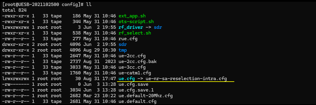
Configured in gnb-sa-reselection-intra.cfg is as shown below. In this configuration, I configured the cell to be a FDD cell (NR_TDD 0) but it doesn’t matter much, you can use whatever you want.
The important part is is to properly configure ncell_list (neighbour cell list) and plmn_list properly. As you see here, cell_id 2 is configured in ncell_list of the cell_id 1 and cell_id 1 is configured in ncell_list of the cell_id 2.
NOTE : In this configuration, I put plmn_list into nr_cell_list block instead of nr_cell_default block. This is to configure the contents of plmn_list differently for each of the cell. In this case, I want to assign different tac (tracking area code) for different cells. Strictly speaking this is not mandatory condition for cell reselection but I wanted to set different tac for each cell to let UE trigger some signalling process (Tracking Area Update in this example) after reselection. Otherwise, UE would perform Cell Reselection but you may not notice it unless you look deep inside of the UE log and find out cell reselection related logging.

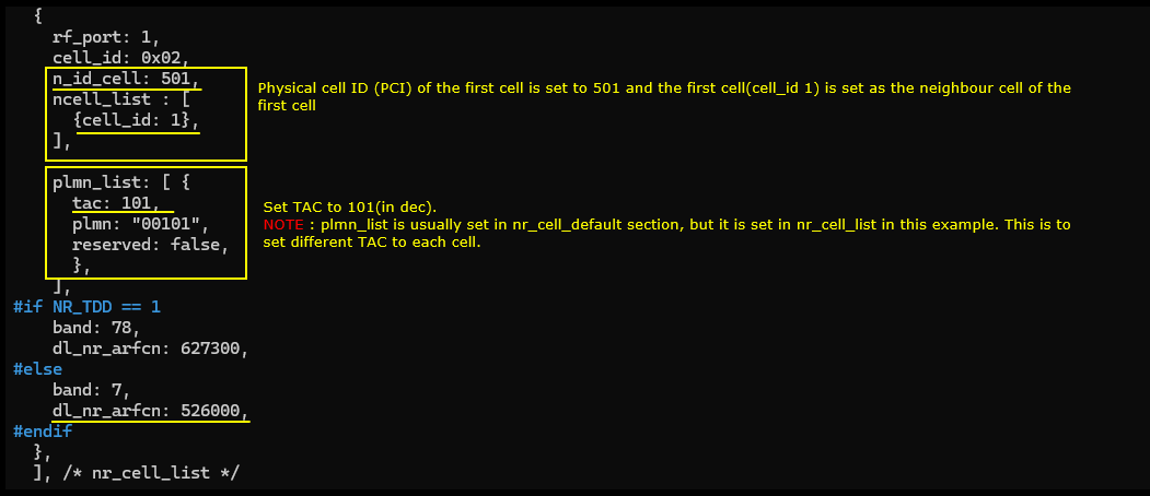
Another important thing is to configure SIB transmission related to intra frequency cell reselection. There are two SIBs related to this process SIB2 and SIB3. I configured the transmission of two external SIB asn files (sib2_nr.asn and sib3_nr.asn) which comes with the installation.
NOTE : strictly speaking, the contents of the SIB3 should be different for each cell, but in this tutorial both cell will transmit the SIB3 with the same contents because it is specified in nr_cell_default block. You would need to set sib_sched_list in nr_cell_list block if you want to configure the contents differently for each cell
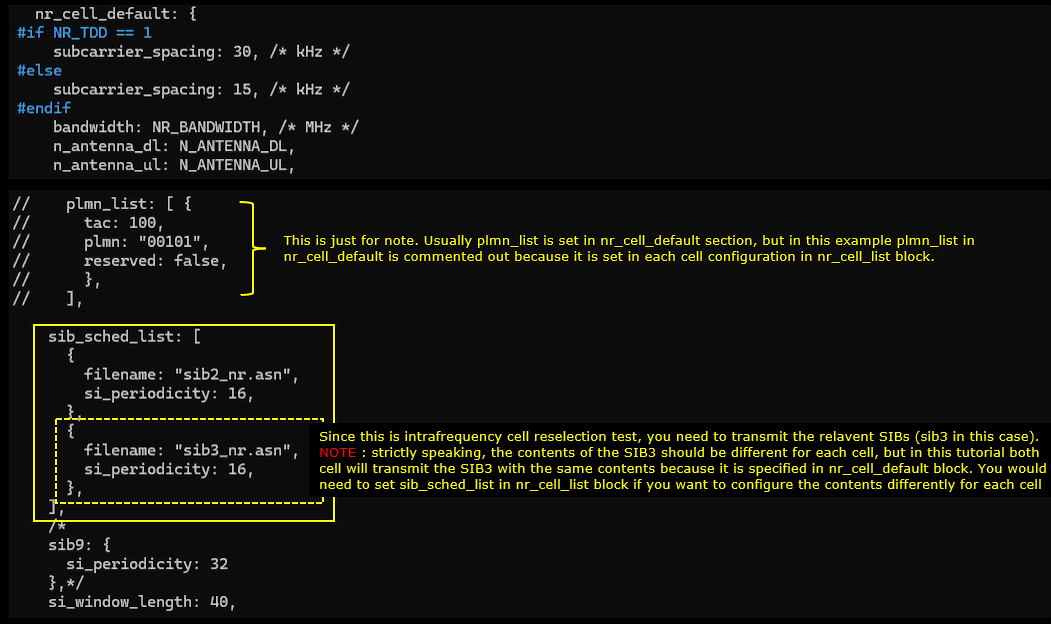
This is the contents of SIB3 (sib3_nr.asn). Assuming that the first cell (PCI 500) is the serving cell, I set physCellId 501 (PCI 501) as the neighbour cell.
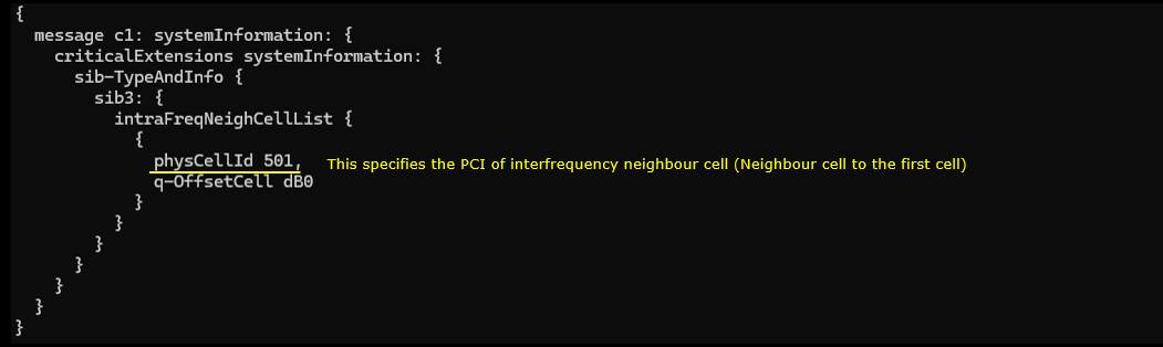
Configured in ue-nr-sa-reselection-intra.cfg is as shown below. UEsim side configuration is very simple. I just set the TDD 0 to set it for FDD which is supposed to match with gNB configuration. And set band, dl_nr_arfcn and ssb_nr_arfcn according to gNB configuration. Everything else I just leave it as in default. All the necessary configuration will be automatically configured by RRC message that gNB send out.
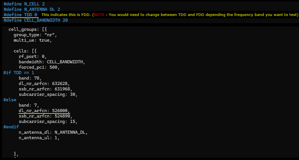
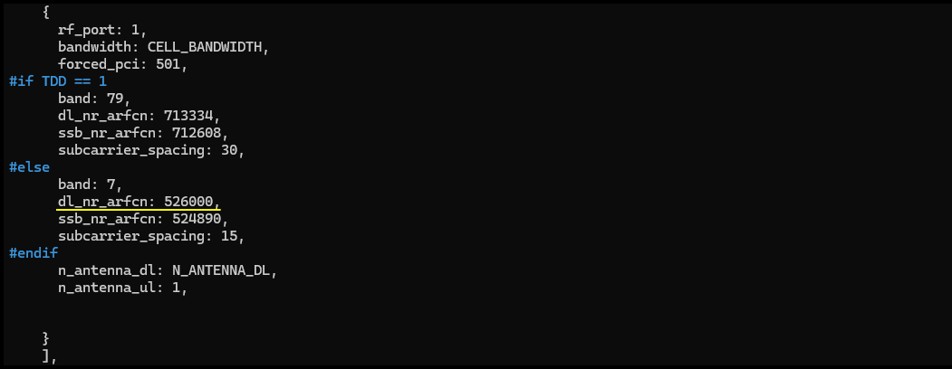
Perform the Test
You may need to pay a little bit closer attention to test execution process because you need to make it sure that you properly configured gNB to trigger cell reselection on UE side.
First it is always a good idea to check cell phy and cell configuration and make it sure that all the cells are configured as intended. One thing I want to highlight here is that cell 1 and cell 2 have different TAC to trigger some signalling (Tracking Area Update in this case) after the cell reselection.

First, I decreased the power of cell 2 lower. This is to make it sure that the UE camp onto cell 1 on power-on. (NOTE : I used the command cell_gain instead of tx_gain to change the cell power. This is because I want to change the cell power without changing cell reference power in SIB). After the command, you see the dl_gain is changed to -40 (dB) for cell 2.
NOTE How much power you should decrease the cell 2 would vary depending on your test setup. In this case, I tried to decrease the cell 2 power in a little large amount but not too large to make the cell undetectable.
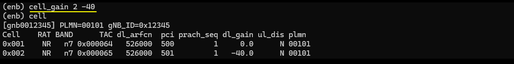
Now on UEsim side, it would be good idea to try ‘cells’ command and make it sure that both of the cells are detected (If you see PCI printed, it mean at least PSS/SSS of the cell is detected and basic PHY sync is established).
NOTE If you are using regular UE as a DUT, you just skip this part and power UE.
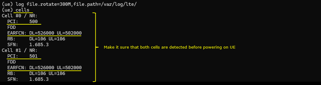
Power on UE and let it complete the attach. Note that UE is connected to Cell 1 (The first cell in this test).
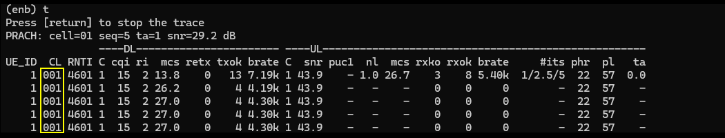
Once UE is in Idle mode, change the cell power to trigger cell reselection. You may increase the power of the second cell and decrease the power of the first cell.
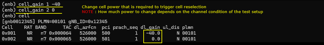
If the reselection is performed on UE side, UE would go through registration process for tracking area code update and you will see the connected cell id is changed to 2.
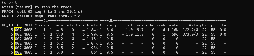
Log Analysis
For cell reselection process, you wouldn’t see anything much from gNB log since basically the cell selection is UE side process. So if cell reselection is not done, in most case you need to look into UE side log for troubleshoot. Even when there is issues with gNB (e.g., cell power is not properly configured to trigger the cell reselection, it is hard to find this from gNB log), you would need to check the measured cell power on UE side log.
UEsim
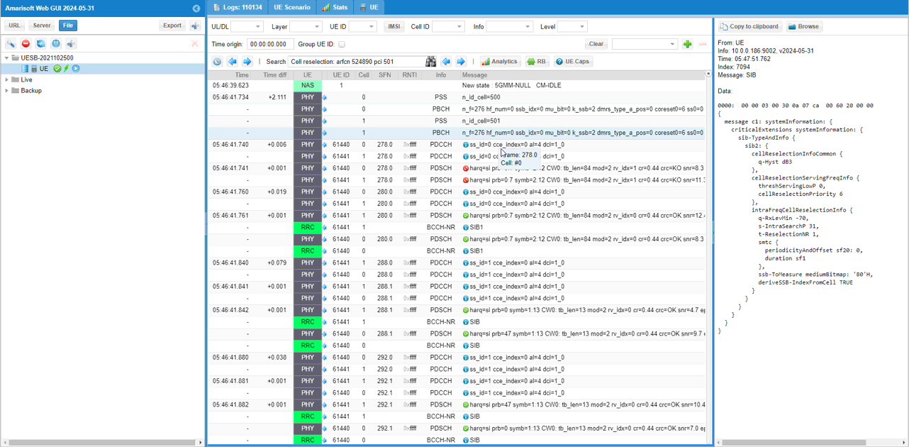
First check if TAC (Tracking Are Code) is configured in SIB1 of the first cell as intended.
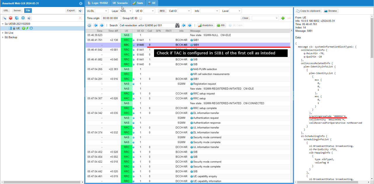
Then make it sure the TAC of the second cell (target cell in this test) is set differently from the first cell.
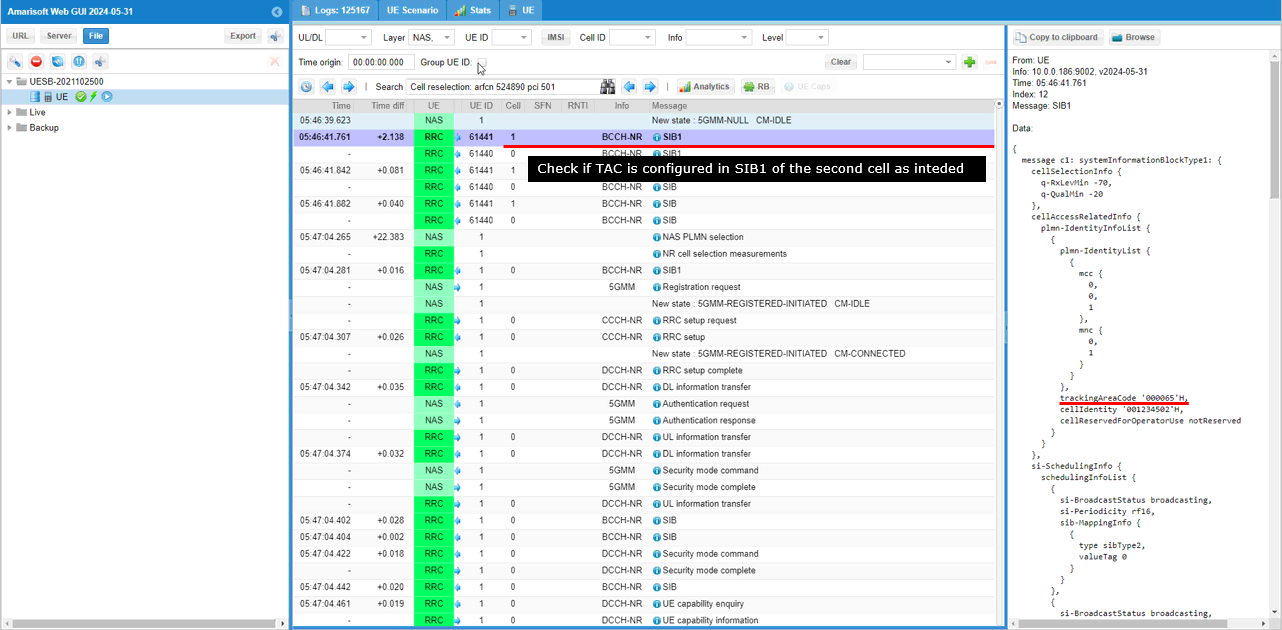
Now check if intra frequency cell reselection criteria for the first cell is configured as intended.
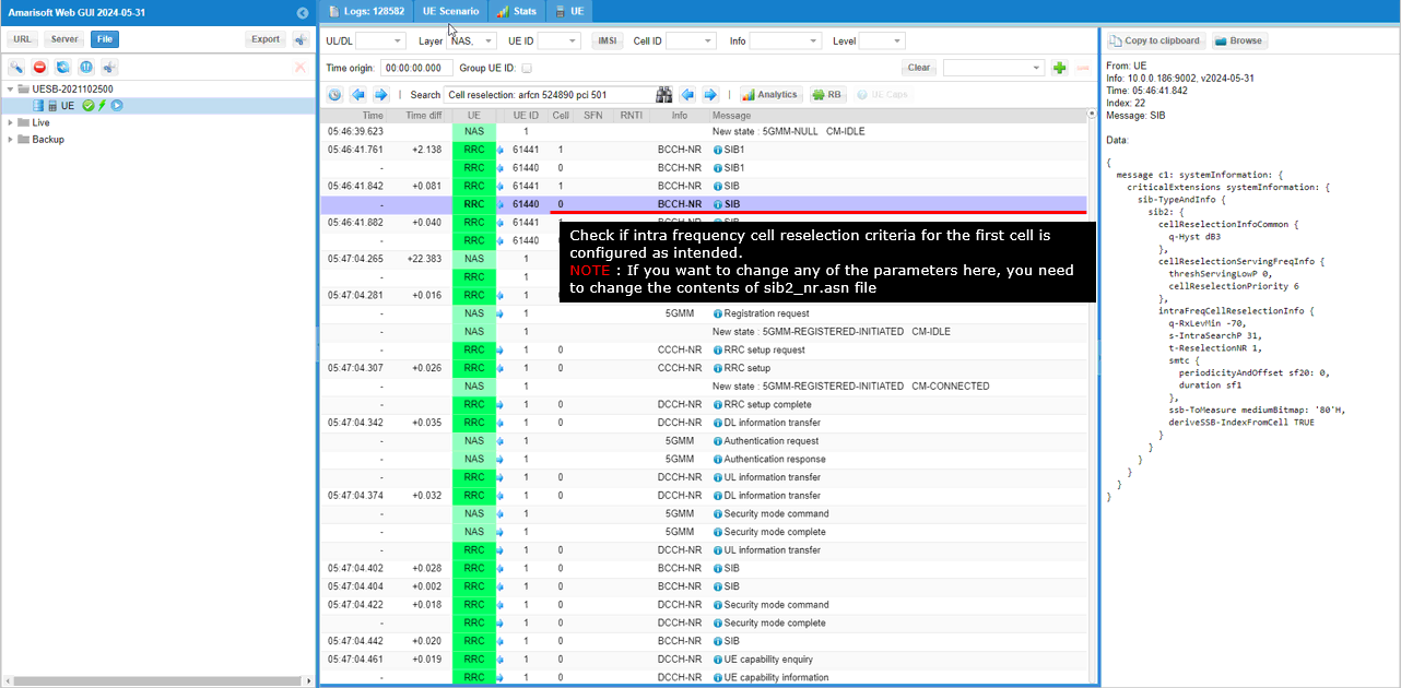
Now make it sure that the neighbour cell of the first cell is configured as intended (NOTE : If you want to change any of the parameters here, you need to change the contents of sib2_nr.asn file which are specified in the enb configuration file).
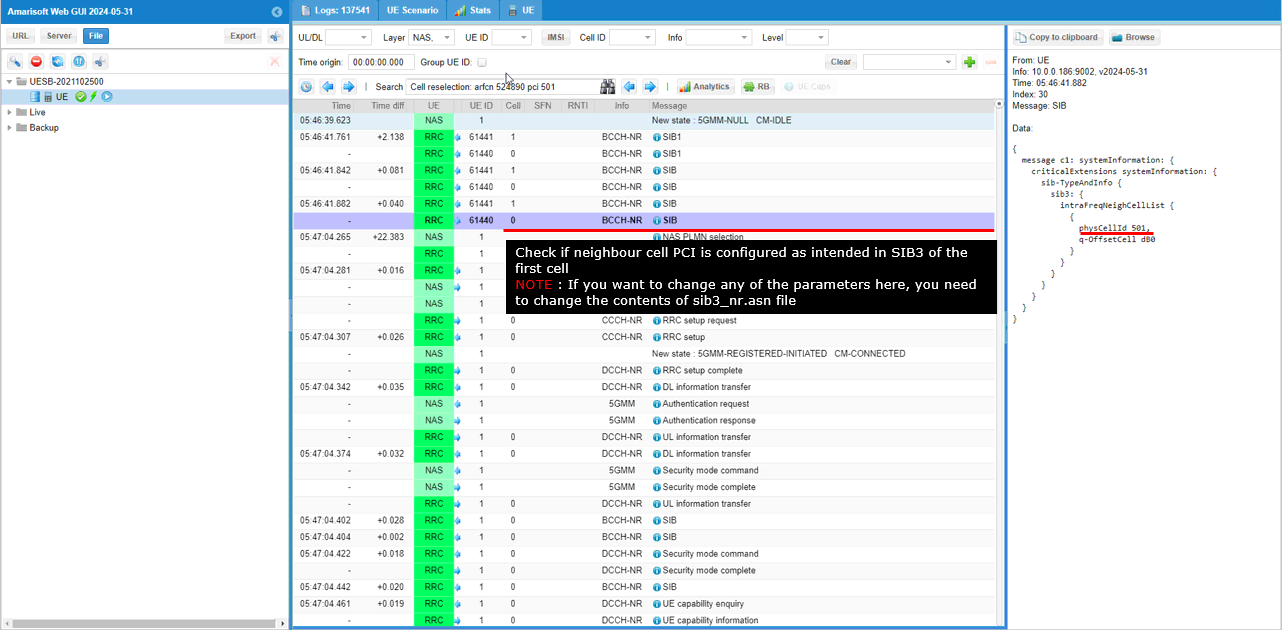
After power_on on UE sim, you would see the logs as follows.
The first step is the result of PLMN selection. It shows that UE selected PLMN 001-01 which is as intended.
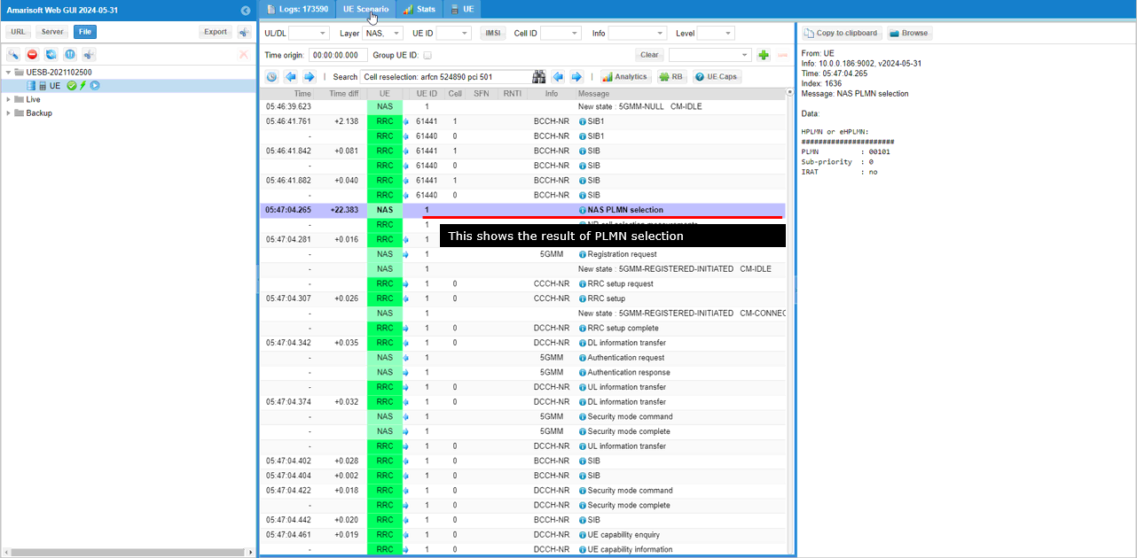
Then UE performs measurement for all the cells it can detect (both the serving cell and neighbour cells) and prints the result as shown here. As you may notice, CableFree UEsim prints out not only rsrp, rsrq but also other parameters like q_rxlev_min, q_qual_min, Srxleve, Squal so that you can easily check if the selection / reselection criteria is met. I think this is a cool feature of CableFree UEsim.
Here you see both cells (Cell #0, Cell #1) meet the criteria of the cell selection, but the rsrp of the first cell (Cell #0) is higher than the second cell, so UE would select to the first cell (Cell #0)
NOTE : If you are using regular phone as a DUT, you also need similar level of information from UE log for troubleshooting.
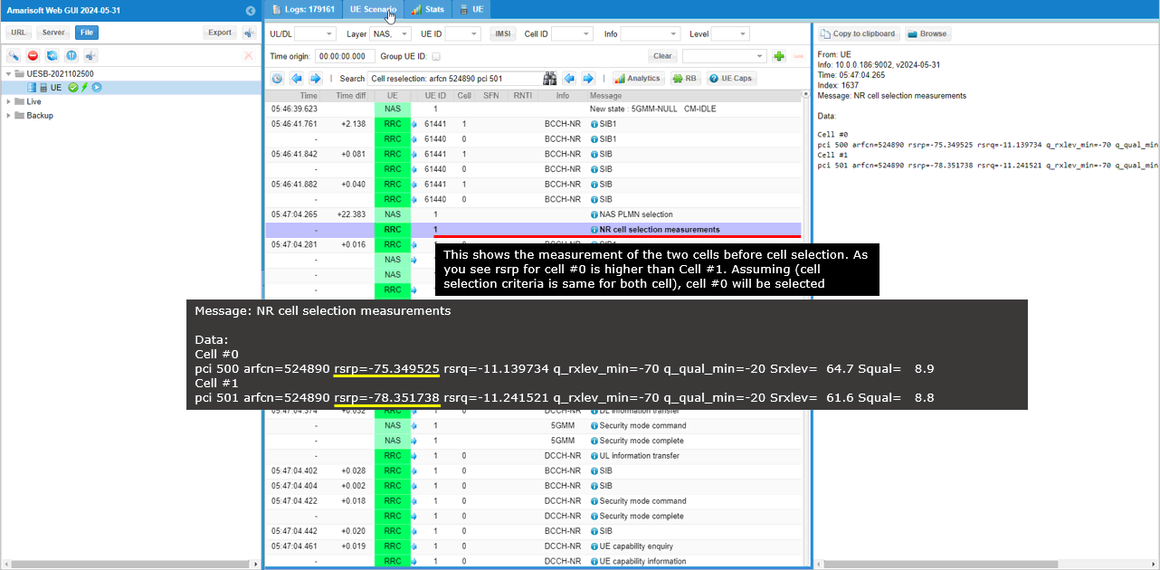
You see that UE is attaching to Cell #0 (the first cell).
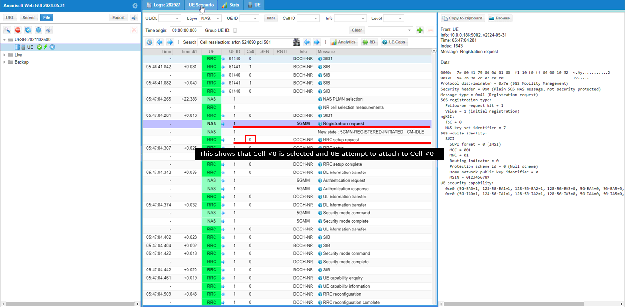
Once UEsim completes the attach process and gets into connected state, UEsim performs connected mode cell measurement and prints the result. This is not important for this tutorial, but it will be important for handover scenario.
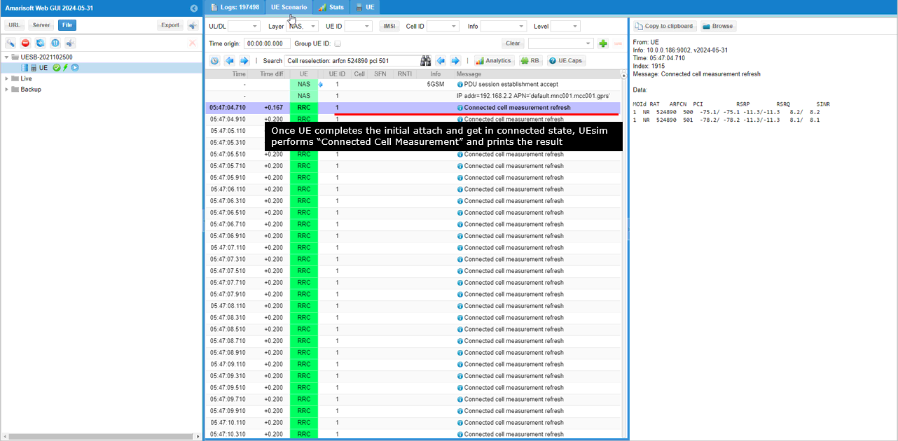
Some time after the initial attach, UE gets into idle mode if there is no traffic from higher layer. Once UE gets into Idle state, UEsim performs “Cell Reselection measurement” and prints the result.
In this specific measurement, PCI 500 cell (the first cell, current serving cell) still has higher RSRP so reselection does not work.
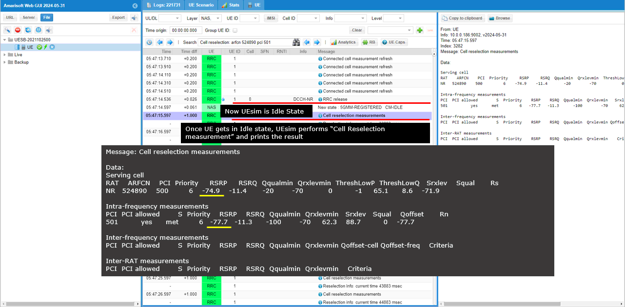
After every measurement, UEsim prints the status of reselection. Since the reselection has not been done, the reselection info shows the PCI of the first cell (PCI 500 in this case).
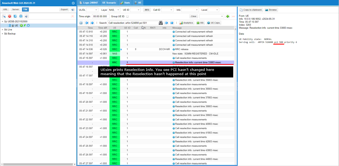
At this point, I changed the cell power of the two cell in such a way that the power of the second cell (PCI 501) gets higher than the first cell (PCI 500).
Now Cell Reselection Measurement result shows that the RSRP of PCI 501 cell is higher than the RSRP of PCI 500 Cell. This meets the reselection criteria and triggers Cell Reselection on UEsim.
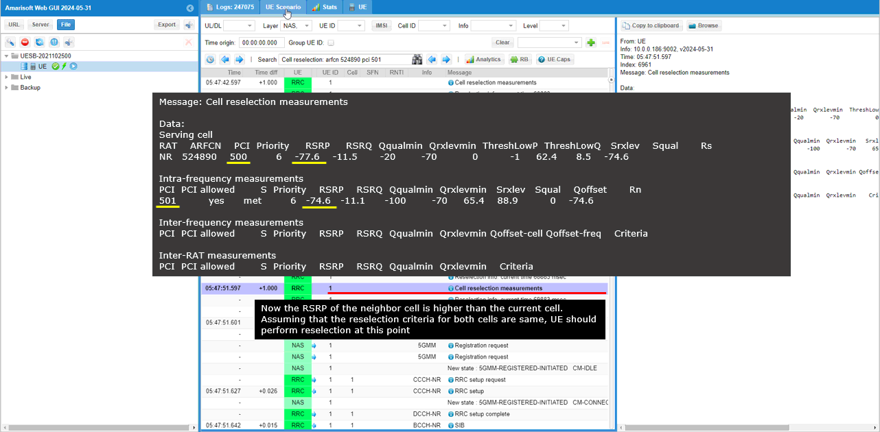
Now the Reselection Info prints the changed PCI which indicates the cell (Serving Cell) changed.
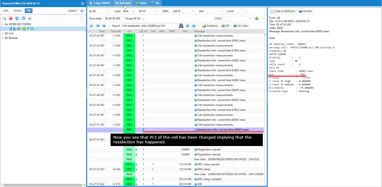
Once reselection is complete, UEsim prints ‘Cell Reselection : arfcn xxxxx and pci xxx’.
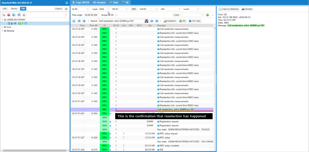
Now UEsim start decoding SIBs for the reselected cell (Cell #1 in this case).
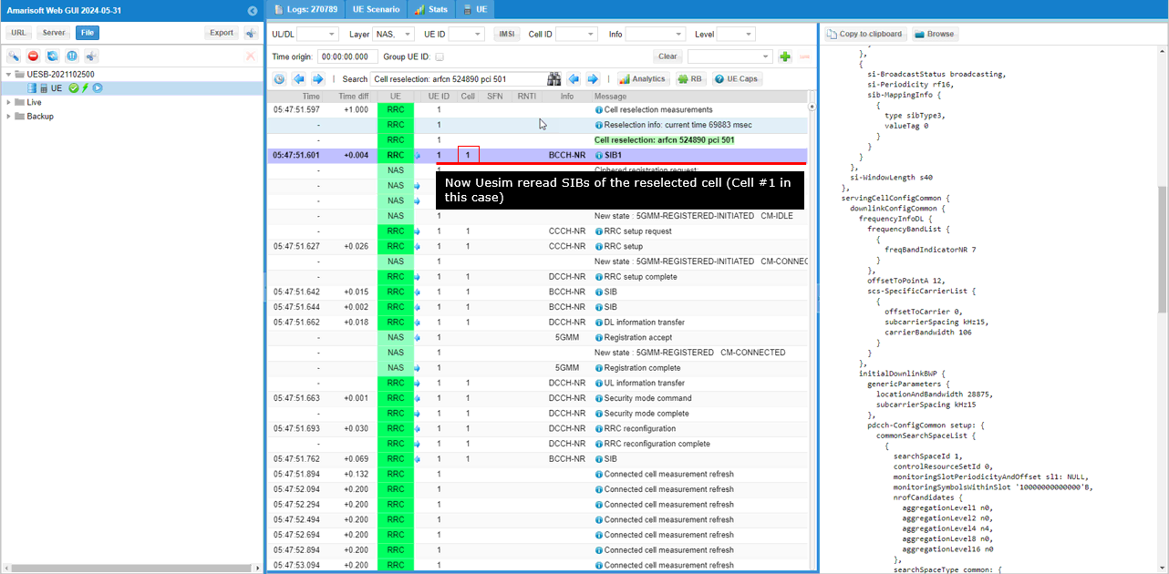
After decoding SIBs, UEsim notice TAC (tracking area code) is different from the previous cell and triggers registration process for TAC update.
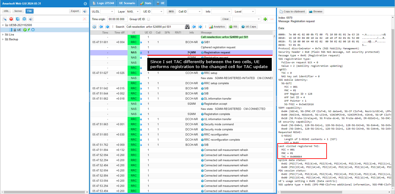
After the tracking area update, UEsim gets into idle mode again and start performing Cell Reselection Measurement.
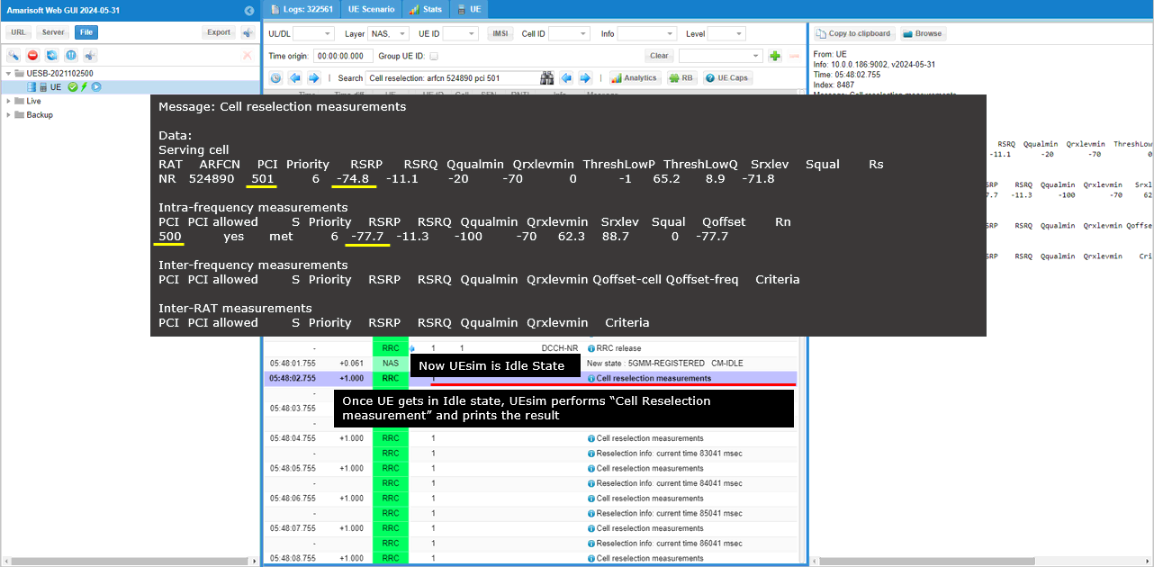
From this point, the same process as explained above repeats.
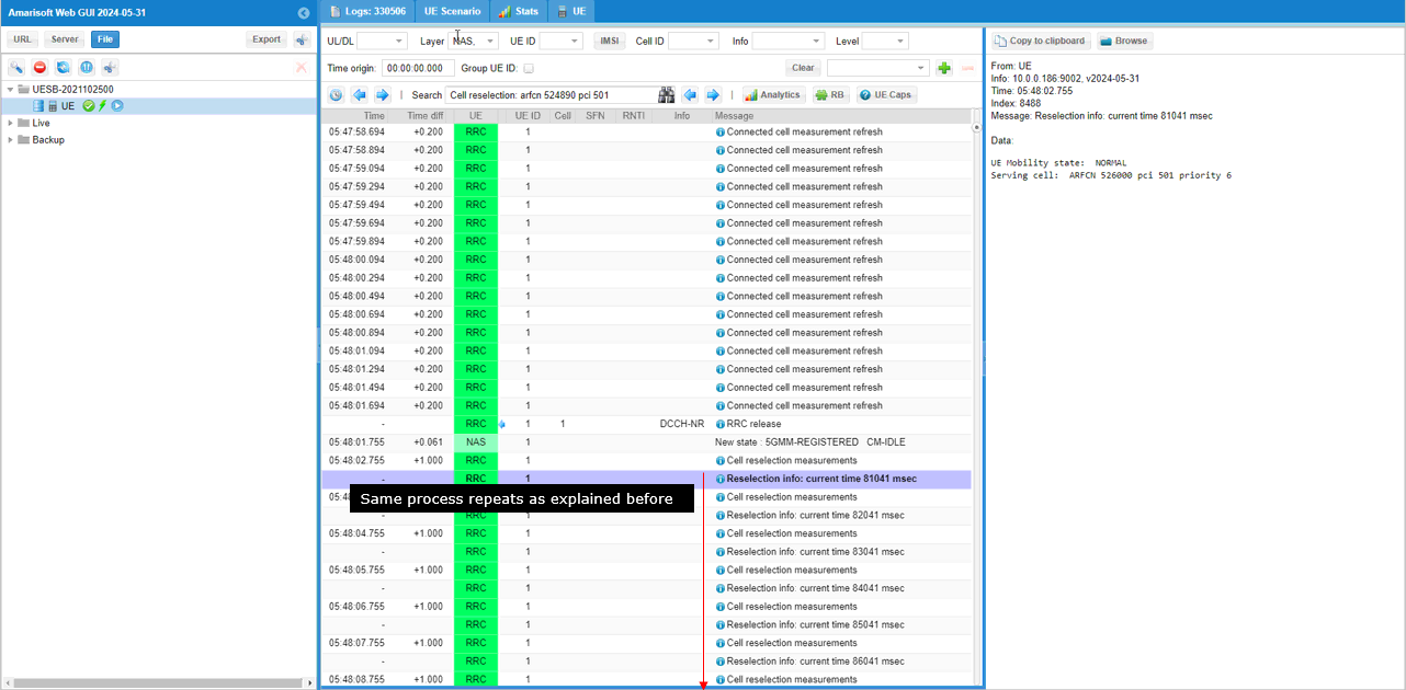
gNB
For the gNB log, I would not put any description since in terms of signalling message it is same as UEsim log. Just as a reference, I put the log only here.
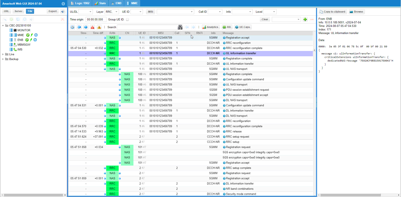
For Further Information
Please contact CableFree Support
support@cablefree.net

Wireless Excellence Limited
NR SA Radio Link Quality Test
This tutorial is a kind of qualitative test rather than exact quantitative test. So don’t pay attention to the exact numbers… just try to get general understandings on radio link quality over the air link between UE and CableFree 5G radio. It will also shows how handy the WebGUI would be for this kind of quick check. You would notice that the range of distance between UE and CableFree 5G radio is pretty wide.
NOTE : Strictly speaking, this test is more of a coverage test for the equipment rather than radio link quality test. The main focus in this test is to check far I can move the DUT away from the equipment without call drop. The conclusion is that the DUT remain connected within 6 m distance without noticeable signal degradation.
NOTE : The wide coverage as shown in this tutorial is suitable only for testing simple attach with lower data rate and for most of protocol function test, but it would not be good for high throughput test. If you want to achieve max (or near max) data throughput the distance between UE and CableFree 5G radio Antenna should be very near or in some cases require RF connection (Conductive) between UE and CableFree 5G radio.
Table of Contents
- NR SA Radio Link Quality Test
- Configuration
- Perform the Test
- Radio Link Quality Change with Distance
- Initial Attach Success Check with Distances
- UL SNR Change with UL Rx Power
Configuration
I have used gnb-sa.cfg which is installed by default without any modification.

I am using the default mme, ims config as shown below.
Perform the Test
The way I perform the test in this tutorial is pretty much different from the case of other tutorials. In this test, you don’t need to do much in terms of the operation of the equipment. Just establishing the connection is all that is required and the remaining part is just to move around with the UE (DUT). In this test, I moved the device farther away and closer to the CableFree 5G radio and observed various signal qualities in WebGUI.
Radio Link Quality Change with Distance
In this test, I checked UL SNR, Data Rate, CQI value as I moved DUT further away from the CableFree 5G radio and moved closer to the CableFree 5G radio. I noticed that overall signal quality (UL SNR) remain in relatively good condition across the entire range of the test.
NOTE : I checked only on Uplink Radio Link Quality because I analysed the data on WebGUI on CableFree 5G radio. If you want to check on the downlink radio link quality, you need to analyse the signal on UE sim (or other signal analyser).

The throughput in this test looks very spiky. It is because the throughput generated in this test is ping. It is just to maintain the call connection with the minimum throughput demand.

Since I am analysing the signal quality from CableFree 5G radio, I can do analysis of the signal quality with direct measurement only for uplink and no direct measurement for downlink. But we can at least get some indirect indicator for downlink signal quality by checking CQI report from UE. The observed result is that there is no significant drops for downlink signal quality to cause call drop but fluctuation seems wider when the DUT is moving.

Initial Attach Success Check with Distances
In this test, I tried initial attach (Power Off and Power On UE) at various distances.
NOTE : The purpose this test is just to show how to do quick check on signal quality. It is not to provide strictly verified test result. I just tried each of the test only once and didn’t do repetitive test for statistical analysis. So some test results would show a little bit counter intuitive results.
At the distance 6 m away from the CableFree 5G radio, SNR is observed relatively lower. However DL retx and UL rxko rate is not much different from other cases. (NOTE : if you push high throughput, you would see obvious differences in terms of retx and rxko)

At the distance 4 m away from the CableFree 5G radio, SNR is much higher compared to the case of 6 m distance. However DL retx and UL rxko rate is not much different from other cases.

At the distance 2 m away from the CableFree 5G radio, SNR is much higher compared to the case of 6 m distance, but it is lower than 4m case (this is a counter intuitive but it may just be test variation). DL retx and UL rxko rate is not much different from other cases.

At the distance 1 m away from the CableFree 5G radio, SNR is higher comparing to any other cases which is as expected.

UL SNR Change with UL Rx Power
In this test, I changed UL EPRE by changing rx_gain on CableFree 5G radio and checking how UL SNR changes at different UL EPRE. EPRE drops strictly according to rx_gain drops, but SNR does stay same (no drop) within relatively wide range of EPRE drop.

For Further Information
Please contact CableFree Support
support@cablefree.net

Wireless Excellence Limited
Out of the Box Test – NR NSA
The purpose of this tutorial is to show you how to establish NR NSA connectivity between a UE and CableFree 5G radio. It is assumed that you don’t have any previous experience with CableFree 5G radio.
NSA stands for “Non-Stand Alone”. In NR NSA implies a few things as below:
- It supports NR with help of other technology (e.g, LTE). In the most common form of NSA called ENDC, NR is supported with the help of LTE. In this configuration, LTE plays a role as an anchor (MCG) which performs the initial attach and most of signalling and NR plays a role as secondary cell (SCG) which provides additional pipe for user traffic.
- (In ENDC) NR Core is not supported and NR is directly/indirectly connected to LTE Core.
According to NR deployment options described in RP-161266, There are many different forms of NSA is defined in this document, but when we say ‘NSA’ as of now, it usually mean Option 3.x (i.e, Option 3 and/or Option 3a) (NOTE : The terminology of these options is not explicitly used in the 3GPP final TS, but the terms (e.g, option 2), option 3.x) etc are widely used in the industry). In CableFree 5G radio, the single core network named ‘mme’ supports both LTE core network and NR core network.

In terms of the frequency and bands, CableFree 5G radio (gNB) supports all the frequencies and bands that are specified in 3GPP. In terms of bandwidth, CableFree 5G radio (gNB) support any 3gpp defined band up to 100Mhz per component carrier as of now.
Test Procedure Summary
This test requires gNB configuration change only and you can keep mme, ims configuration as in default.
Step 1 : specify gnb-nsa.cfg as enb configuration (i.e, run ‘ln -sf gnb-nsa.cfg enb.cfg’ in /root/enb/config). If you want to change the configuration of gnb-nsa.cfg, I would suggest to copy enb.default.cfg to a new file and specify the copied file as enb configuration)
Step 2 : Set TDD/FDD for LTE (TDD) and for NR(NR_TDD). number of DL Antenna for LTE(N_ANTENNA_DL_LTE), number of DL Antenna for NR(N_ANTENNA_DL_NR), Bandwidth for LTE(N_RB_DL) and Bandwidth for NR(NR_BANDWIDTH) as you want
Step 3 : If you want to change frequency specify dl_earfcn for LTE, change band and dl_nr_arfcn for NR as you want. If you change NR frequency, don’t forget to change SSB frequency (ssb_nr_arfcn) accordingly.
Step 4 : Run the test (i.e, run ‘service lte restart’)
Step 5 : Run Screen (i.e, run ‘screen -r’)
Step 6 : Select eNB component (i.e, press Alt+A+1)
Step 7 : Power on UE and Verify the result with ‘t’ command and the captured Log.
NOTE : If your UE support NSA with the band n78, the gnb-nsa.cfg is expected to work without any modification.
Table of Contents
- Out of the Box Test – NR NSA
- Test Procedure Summary
- Test Setup
- Key Configuration Parameters
- Test 1 : Basic NSA (Single LTE + Single NR)
- Configuration
- Check if LTE service is Running
- Perform the Test
- Log Analysis
- Generating Traffic
- Analysis in Screen during traffic test
- Traffic Analysis on WebGUI
- Test 2 : 6 LTE CA + Single NR
- Configuration
- 1st LTE Cell
- 2nd LTE Cell
- 3rd LTE Cell
- 4th LTE Cell
- 5th LTE Cell
- 6th LTE Cell
- Common to All LTE Cell
- NR Cell
- Perform the Test
- Log Analysis
- Configuration
- Test 3 : 5 LTE CA(FDD + TDD) + Single NR
- Configuration
- Global Parameters
- 1st LTE Cell
- 2nd LTE Cell
- 3rd LTE Cell
- 4th LTE Cell
- 5th LTE Cell
- NR Cell
- Common to All LTE Cell
- Perform the Test
- Log Analysis
- Configuration
- RRC / NAS Signalling
- rrcConnectionReconfiguration for NR Addition
- Tips
- Changing Configuration File
- Troubleshoot
- Requirement for UE Capability Information
- Requirement for UE Network Capability
- Requirement for UE Capability Enquiry
- Requirement for measurement request
- Requirement for NR addition
- Common Issues
- Unintended Measurement Configuration
- Unintended Measurement Event Configuration
- No Measurement Report
- SCG Failure
- Requirement for UE Capability Information
Test Setup
- Since this test is for Out of the box testing, I used the default nsa configuration(gnb-nsa.cfg) file without changing anything in it
- SIM Card used in this tutorial is the one delivered with the system as it is.
Key Configuration Parameters
Followings are important configuration parameters for this tutorial.
- cell_list
- en_dc_scg_cell_list
- en_dc_support
- cell_default
- nr_cell_list
- band
- dl_nr_arfcn
- subcarrier_spacing
- ssb_pos_bitmap
- nr_cell_default
- bandwidth
- n_antenna_dl
- n_antenna_ul
- tdd_ul_dl_config
- ssb_period
- meas_config_desc :
- a1_report_type
- a1_rsrp
- a1_hysteresis
- a1_time_to_trigger
- a2_report_type
- a2_rsrp
- a2_hysteresis
- a2_time_to_trigger
- a3_report_type
- a3_offset
- a3_hysteresis
- a3_time_to_trigger
- rsrp_filter_coeff
- nr_b1_report_type
- nr_b1_rsrp
- nr_b1_hysteresis
- nr_b1_time_to_trigger
- nr_rsrp_filter_coeff
- meas_gap_config
Test 1 : Basic NSA (Single LTE + Single NR)
This is the simplest and the most basic test for NSA which involves only one LTE Cell and only one NR Cell. The main purpose is to introduce basic operation with default sample configuration.
Configuration
By default, CableFree 5G radio uses enb.cfg for eNB/gNB configuration. This default configuration is configured for LTE band 3, band 4. If you want to use the CableFree 5G radio for other RAT (Radio Access Technology) like 5G or other LTE bands (i.e, bands other than band 3, 7), you need to change the configuration.
In this section, I would show you how to change the configuration file that is used by eNB/gNB. But in this very basic tutorial (Out of the Box Test), I would not try to change the detailed configuration within the file and will just replace the enb.cfg with another file.
Go to eNB/gNB configuration directory

change the symbolic link so that enb.cfg points to { enb.cfg -> gnb-nsa.cfg } using following command

Now you should see the enb.cfg is linked to gnb-nsa.cfg as shown below. (NOTE : If you want to change the contents of configuration file as per your own test requirement, refer to Tips : Changing Configuration File)

Now go to the directory /root/mme/config. You should see the configuration files as below.

If ims.cfg and mme.cfg is not linked to the files as shown above, you may run following commands to make proper link.

Restart the CableFree 5G radio so that the new configuration file is applied

Check if LTE service is Running
Whatever you want to test, the first thing you need to do is that CableFree 5G radio program (LTE Service) is running. You can check on the execution status of the CableFree 5G radio program by running following command and you should get the result as shown below
- # service lte status

NOTE : Getting this result is pre-requisite for Call Box Operation, but this result itself does not guarantee the normal operation. If you see some unexpected issues, you may restart the CableFree 5G radio with the following command
# service lte restart
Perform the Test
If it is confirmed that the lte service is running, go to screen mode by running ‘screen -r’ and follow through the steps as shown below. The steps shown here is the procedure that you would use for almost every test and it is highly recommended to get familiar with these steps.
First open the screen window with the ‘screen’ command. (NOTE : You might have seen ‘screen -x’ in other documents. ‘screen -x’ mean ‘simultaneous screen attach, ‘screen -r’ mean ‘resume attach (attach to the detached screen)’ There are slight difference between them but in most case you would have same result. You may google or ask AI for further details if you are interested)

You will get the screen as shown below. This screen shows all the network components installed in the CableFree 5G radio. In this tutorial, it indicates MME, ENB, IMS, MBMSGW are installed in the CableFree 5G radio.
You would see a number before each component name. With Ctrl+A and the number before the component name, you can switch to command line window for the specific component. For example, if you press Ctrl+A+1, the command line window switches to ENB and if you press Ctrl+A+0, the command line window switches to MME and so on.

Switch to [ENB] by pressing { Ctrl + A + 1 }. You will get the screen as shown below
When you switches to [ENB] there are some important information provided without running any specific command. It provides RF information showing the sample_rate, dl_freq, ul_freq, band, dl_ant, ul_ant that gives you very fundamental RF information. Check out the details of these info and see if the RF is configured as you intended.

You can confirm the cell configuration (e.g, RAT type, BW, frequency etc) using cell commands.
If you run ‘cell phy’ command, you will get the basic physical configuration for the cells that are configured in the test. RAT, BAND, BW, ARFCN, SCS are the most common items to be checked before you move on with the test.

If you run ‘cell main’ or just ‘cell’ command, you will get some additional information that is not shown with ‘cell phy’, for example, PCI, TAC, plmn and dl_gain.

Start trace logging by ‘t’ command as shown below .

Power On UE and let it complete the attach and NSA establishment. You would get trace as shown below. (NOTE : If you don’t see PRACH to cell=02, it mean NSA establish failed and you need to check the log to find out the root cause).

Press [Enter] key to stop the trace logging. When you want to use another command, you need to stop ‘t’ command by pressing the enter key and get back to prompt as shown below.

While UE is in connected status, you can get the connection information with the command ‘ue’ in (enb) as shown below. If the call is in idle status, you would not get any information.

you can get the connection information with the command ‘ue’ in (mme) as shown below. You would get this result once UE complete the attach. One important information you would get is the IP address assigned to the UE.

Log Analysis
In this section, you will see how to confirm if UE is established with NSA. I will skip the initial registration part and focus only on NSA setup.
NOTE : This section is just to check quickly some important points in the log, but it may be a little bit tricky to do the detailed log analysis (especially for lower layer log analysis). In that case, I strongly recommend you to use WebGUI for the log analysis.
Open /tmp/gnb0.log using any text editor. I am using nano in this tutorial. You will see various high level information (meta data) at the beginning of the file. This is useful high level information.

After the attach to LTE is completed, you should see that eNB send Measurement Report Configuration for NR cell as shown below. If you don’t see this message, it is highly likely that UE does not notify NR support in UE capability or UE support NR but does not support band combination you specified in the configuration file.

If you support the LTE-NR band combination specified above and NR cell is properly configured, you should see the measurement report for NR as shown below. If UE does not send this measurement report, eNB does not send RrcConnectionReconfiguration message for NR addition. This is one of the most common causes for NSA failure.

If the measurement report from UE is received, (in most cases) eNB send RrcConnectionReconfiguration to add NR cell as shown below.


If UE received the RrcConnectionReconfiguration and processed it successfully, UE send RrcConnectionReconfigurationComplete message.

Now UE and Network perform RACH procedure to establish the connection to NR cell. This RACH procedure is a 5 step process as shown below. If the process fails any of these steps, NSA establish fails.


Generating Traffic
Once UE established NSA and in connected mode, you may generate IP traffic for throughput test. There are many different ways to generate IP traffic. In this tutorial, I simply opened up a browser on UE and visited speedtest site.

Analysis in Screen during traffic test
During the traffic test, we usually check some status in Screen window for checking throughput or troubleshoot. Followings are three most common command that we use for check up. If you are not familiar with the meaning or interpretation of these commands.
With t command, you can check various things. For the quick check on connectivity, just checking the throughput indicated by ‘brate’ column would be good enough.

If you think you have any power related issues for example TX and RX power, run ‘t spl’. This is especially useful to troubleshoot the receiver power related issue.

If you think you have issues related to performance (e.g, timing issue or overflow issue), run ‘t cpu’. This is especially useful to troubleshoot the case when you have ‘overflow’ issue.

Traffic Analysis on WebGUI
This is an optional section. You may try high throughput test and analyse it with WebGUI.
What kind of analysis to be checked is up to you, but a few examples shown in this tutorial would be the most common analysis you may check.
First thing you may want to check out is the throughput plot. The tool menu on the analysis screen would vary depending on the software version you are using an older version of the software, you would get the plot window right away when you clicking on [ENB] button. Hit on [Bitrate] tab to get the throughput plot.

If you are using the relatively recent version, hit [Analysis] button first and then you get the plot window. Select [Throughput] tab to get the throughput plot.

If you hit [TX RETX] tab, you will get the plots for the count of retransmitted packet. This plot shows how many packets failed to be decoded by the receiver and retransmitted.

In addition to these plots mentioned above, there are various additional analysis features are supported by WebGUI.
Test 2 : 6 LTE CA + Single NR
This is a kind of advanced test of NSA and I assume that the readers are already familiar with basic operations and overall verification procedures explained in Test 1. With that assumption, I would mainly focus on RAN side configuration and verification only. You can follow the procedure in Test 1 for user traffic.
NOTE : This test involves many cells. 7 cells in total. Before you try this, first make it sure that you have enough hardware resources (i.e, enough number of radio front ends and PC performance).
- The best option is that you have 7 radio front ends.
- If you don’t have enough number of radio front ends, you may put multiple cells in one radio front end if the frequency and RAT requirement is met.
Configuration
The configuration for this test is gnb-6LTE-1NR-nsa.cfg which is based on gnb-nsa.cfg. It may look complicated but it is just repetition of the same structure with minor modifications.
Following is the configurations for 6 LTE cells.
1st LTE Cell
1st LTE cell is mapped to rf_port 0 and configured for FDD. dl_earfcn is set to 300. 5 LTE cells (cell id 2,3,4,5,6) are configured as SCC (Secondary Component Carrier) and one NR cell (cell id 7) is configured as SCG (Secondary Cell Group).

2nd LTE Cell
2nd LTE cell is mapped to rf_port 1 and configured for FDD. dl_earfcn is set to 1476. 5 LTE cells (cell id 1,3,4,5,6) are configured as SCC (Secondary Component Carrier) and one NR cell (cell id 7) is configured as SCG (Secondary Cell Group).

3rd LTE Cell
3rd LTE cell is mapped to rf_port 2 and configured for FDD. dl_earfcn is set to 1674. 5 LTE cells (cell id 1,2,4,5,6) are configured as SCC (Secondary Component Carrier) and one NR cell (cell id 7) is configured as SCG (Secondary Cell Group).

4th LTE Cell
4th LTE cell is mapped to rf_port 3 and configured for FDD. dl_earfcn is set to 3001. 5 LTE cells (cell id 1,2,3,5,6) are configured as SCC (Secondary Component Carrier) and one NR cell (cell id 7) is configured as SCG (Secondary Cell Group).

5th LTE Cell
5th LTE cell is mapped to rf_port 4 and configured for FDD. dl_earfcn is set to 3199. 5 LTE cells (cell id 1,2,3,4,6) are configured as SCC (Secondary Component Carrier) and one NR cell (cell id 7) is configured as SCG (Secondary Cell Group).

6th LTE Cell
6th LTE cell is mapped to rf_port 5 and configured for FDD. dl_earfcn is set to 9435. 5 LTE cells (cell id 1,2,3,4,5) are configured as SCC (Secondary Component Carrier) and one NR cell (cell id 7) is configured as SCG (Secondary Cell Group).

Common to All LTE Cell
For all LTE cell, the measurement configuration for NR cell (Event B1) is configured. The presence of this configuration indicates Measurement Report from UE is required to trigger NR Addition.

NR Cell
One NR cell is configured and it is mapped to rf_port 6. It is configured as TDD, band n78 and dl_nr_arfcn 636666.

Perform the Test
Check cell phy and cell command output, and see if all the cells are configured as intended.


Run ‘t’ command and get UE attached and wait until NR cell is added.

Log Analysis
Check out every detail in the log. It will help you with understanding LTE CA and NSA protocol and troubleshoot process.
First thing you need to check in any carrier aggregation test is UE capability enquiry. You see an UE capability enquiry for LTE band 1, 3, 7, 28 was sent.

Check out the contents of UE capability information message from UE. It would be easier to check it out with UE capability table rather than looking into the UE capability information RRC message itself. Ensure that the UE (DUT) supports LTE CA.

For NSA capability check, another UE capability enquiry was sent with nr n78 and lte b1,3,7,28.

Check out the contents of UE capability information message from UE. It would be easier to check it out with UE capability table rather than looking into the UE capability information RRC message itself. Ensure that the UE (DUT) supports ENDC.

If UE capability information carries the band combination that is necessary to establish the desired carrier aggregation and NSA (endc), eNB configures measurement report. In this example, the measurements for carrierFreq 300,1476,1674,3001,3199,9435 are configured.

Measurement for NR cell with the carrierfreq of 633696 is configured as well. The frequency set is SSB frequency of the target NR cell. Then report configuration for even B1 is set.

Finally measObjectId 7 (NR measurement in this configuration) and reportConfigId 1 (Event B1 in this configuration) is triggered.

In the same RRCconnectionReconfiguration message, LTE cell id 2 is added as SCC 1 (sCellIndex-r10 1).

In the same RRCconnectionReconfiguration message, LTE cell id 3 is added as SCC 2 (sCellIndex-r10 2).

In the same RRCconnectionReconfiguration message, LTE cell id 4 is added as SCC 3 (sCellIndex-r10 3).

In the same RRCconnectionReconfiguration message, LTE cell id 5 is added as SCC 4 (sCellIndex-r10 4).

In the same RRCconnectionReconfiguration message, LTE cell id 6 is added as SCC 5 (sCellIndex-r10 5).

In the same RRCconnectionReconfiguration message, nr0RadioBearerConfig1-r15 is configured.

Once all the RRC processes are processed properly, MAC CE to enable SCC 1,2,3,4,5 are sent.

UE is expected to send measurement report for NR cell after setting up LTE Carrier Aggregation.

Once eNB receives the measurement report for NR cell, eNB send RRCconnectionReconfiguration to establish NSA(endc).

You can confirm that n78 and PCI 500 NR cell is added as SCG (Secondary Cell Group).

You can confirm the addition of NR cell by checking if RACH process in NR is completed. This is an important step since this is where NSA setup failure happens frequently.

Test 3 : 5 LTE CA(FDD + TDD) + Single NR
This is a kind of advanced test of NSA and I assume that the readers are already familiar with basic operations and overall verification procedures explained in Test 1. With that assumption, I would mainly focus on RAN side configuration and verification only. You can follow the procedure in Test 1 for user traffic.
NOTE : This test involves many cells. 6 cells in total. Before you try this, first make it sure that you have enough hardware resources (i.e, enough number of radio front ends and PC performance).
- The best option is that you have 6 radio front ends.
- If you don’t have enough number of radio front ends, you may put multiple cells in one radio front end if the frequency and RAT requirement is met.
Configuration
The configuration for this test is gnb-cc-mix_TDD_FDD-nsa.cfg which is based on gnb-nsa.cfg. It may look complicated but it is just repetition of the same structure with minor modifications.
Following is the configurations for 5 LTE cells. The key point to be noticed in this configuration is that not all LTE cells uses the same duplex pattern. It is mixture of FDD and TDD. Some of them are using FDD and some of them are using TDD.
Global Parameters
At the beginning, several flags (parameters) are added to let user to apply duplex mode and bandwidth differently for each LTE cells. These parameters are needed because the cells in carrier aggregation in this tutorial is mixture of FDD and TDD.

1st LTE Cell
Then configure the physical parameters of the first LTE cell. This cell is mapped to rf_port 0. This cell is configured for FDD and dl_earfcn is 800.

One NR cell (cell id 6) is configured as SCG (Secondary Cell Group) and 4 LTE cells (cell id 2,3,4,5) are configured as SCC (Secondary Component Carrier).

This cell is configured as FDD, so TDD specific configuration is not applied.

2nd LTE Cell
Next, configure the physical parameters of the 2nd LTE cell. This cell is mapped to rf_port 1. This cell is configured for TDD and dl_earfcn is 47290.

One NR cell (cell id 6) is configured as SCG (Secondary Cell Group) and 4 LTE cells (cell id 1,3,4,5) are configured as SCC (Secondary Component Carrier).

This cell is configured as TDD. uldl_config is set to 2 and sp_config is set to 7. tdd_ack_nack_feedback_mode_r10 is set to “cs” and tdd_ack_nack_feedback_mode is set to “multiplexing”.

3rd LTE Cell
Next, configure the physical parameters of the 3rd LTE cell. This cell is mapped to rf_port 2. This cell is configured for TDD and dl_earfcn is 47488.

One NR cell (cell id 6) is configured as SCG (Secondary Cell Group) and 4 LTE cells (cell id 1,2,4,5) are configured as SCC (Secondary Component Carrier).

This cell is configured as TDD. uldl_config is set to 2 and sp_config is set to 7. tdd_ack_nack_feedback_mode_r10 is set to “cs” and tdd_ack_nack_feedback_mode is set to “multiplexing”.

4th LTE Cell
Next, configure the physical parameters of the 4th LTE cell. This cell is mapped to rf_port 3. This cell is configured for TDD and dl_earfcn is 47686.

One NR cell (cell id 6) is configured as SCG (Secondary Cell Group) and 4 LTE cells (cell id 1,2,3,5) are configured as SCC (Secondary Component Carrier).

This cell is configured as TDD. uldl_config is set to 2 and sp_config is set to 7. tdd_ack_nack_feedback_mode_r10 is set to “cs” and tdd_ack_nack_feedback_mode is set to “multiplexing”.

5th LTE Cell
Last for LTE cell, configure the physical parameters of the 5th LTE cell. This cell is mapped to rf_port 4. This cell is configured for FDD and dl_earfcn is 66836.

One NR cell (cell id 6) is configured as SCG (Secondary Cell Group) and 4 LTE cells (cell id 1,2,3,4) are configured as SCC (Secondary Component Carrier).

This cell is configured as FDD so TDD specific configuration is not applied.

NR Cell
Now, configure NR cell to be used for NSA setup. NR Cell is configured to TDD, band n78 and dl_nr_arfcn 627300.

Common to All LTE Cell
For configuration that are applied to all of the LTE cell (cell_default), CSI report is set to periodic, Transmission mode is TM3 and Measurement Report (B1) is configured meaning that a proper measurement report is required to initiate NSA setup.

Perform the Test
Check cell phy and cell command output, and see if all the cells are configured as intended.

Run ‘t’ command and get UE attached and wait until NR cell is added. (If you have any issues with NR addition, refer to troubleshoot section).

Log Analysis
Check out every detail in the log. It will help you with understanding LTE CA and NSA protocol and troubleshoot process.
First thing you need to check in any carrier aggregation test is UE capability enquiry. You see an UE capability enquiry for LTE band 2, 46, 66 was sent.

For NSA capability check, another UE capability enquiry was sent with nr n78 and lte b2,46,66.

Check out the contents of UE capability information message from UE. It would be easier to check it out with UE capability table rather than looking into the UE capability information RRC message itself. Ensure that the UE (DUT) supports LTE CA and NSA band combination that you want to establish.

If UE capability information carries the band combination that is necessary to establish the desired carrier aggregation and NSA (endc), eNB configures measurement report. In this example, the measurement for carrierFreq 800,47290,47488,47686,65535 are configured.

Measurement for NR cell with the carrierfreq of 624288 is configured as well. The frequency set is SSB frequency of the target NR cell.

Then report configuration for even B1 is set. Finally measObjectId 6(NR measurement in this configuration) and reportConfigId 1(Event B1 in this configuration) is triggered.

In the same RRCconnectionReconfiguration message, csi report configuration for all the subcarriers of LTE cells are configured.

In the same RRCconnectionReconfiguration message, LTE cell id 2 is added as SCC 1 (sCellIndex-r10 1).

In the same RRCconnectionReconfiguration message, LTE cell id 3 is added as SCC 2 (sCellIndex-r10 2).

In the same RRCconnectionReconfiguration message, LTE cell id 4 is added as SCC 3 (sCellIndex-r10 3).

In the same RRCconnectionReconfiguration message, LTE cell id 5 is added as SCC 4 (sCellIndex-r10 4).

In the same RRCconnectionReconfiguration message, nr0RadioBearerConfig1-r15 is configured.

UE is expected to send a measurement report for NR cell.

Once eNB receives the measurement report for NR cell, eNB send RRCconnectionReconfiguration to establish NSA(endc).

You can confirm that n78 NR cell is added as SCG (Secondary Cell Group)

Once all the RRC processes are processed properly, MAC CE to enable SCC 1,2,3,4 are sent.

You can confirm the addition of NR cell by checking if RACH process in NR is completed. This is an important step since this is where NSA setup failure happens frequently.

Once all LTE carrier aggregation and NR addition is completed, traffic flows and csi report are received for both LTE and NR as set in the configuration file.

RRC / NAS Signaling
This section is to show you the overall structure of important Rrc messages and Information IE (IE) that are related to this tutorial. It is not intended to describe the details on every RRC/NAS Information element. With the overall structure and key IEs shown here, it hope it would be easier / clearer to go through the sample log provided in this tutorial or any logs that you captured from your own test setup or live network.
NOTE : The purpose of this section is to show you the overall structure of the related Rrc messages and some key information elements. It is not to show the every detail of the IE which is too much to be covered.
rrcConnectionReconfiguration for NR Addition
This is the RRC message sent by eNB (LTE) to add NR. (NOTE : You would see some IEs that has a specific assigned vale here, but consider it as just an example value. Those values should vary depending on test requirement).
message c1: rrcConnectionReconfiguration: {
rrc-TransactionIdentifier 0,
criticalExtensions c1: rrcConnectionReconfiguration-r8: {
….
nonCriticalExtension {
nonCriticalExtension {
nonCriticalExtension {
nonCriticalExtension {
nonCriticalExtension {
nonCriticalExtension {
nonCriticalExtension {
nonCriticalExtension {
nr-Config-r15 setup: {
endc-ReleaseAndAdd-r15 FALSE,
nr-SecondaryCellGroupConfig-r15 {
rrc-TransactionIdentifier 0,
criticalExtensions rrcReconfiguration: {
secondaryCellGroup {
cellGroupId 1,
rlc-BearerToAddModList {
…
mac-CellGroupConfig {
…
physicalCellGroupConfig {
pdsch-HARQ-ACK-Codebook dynamic
},
spCellConfig {
servCellIndex 1,
reconfigurationWithSync {
spCellConfigCommon {
physCellId 500,
downlinkConfigCommon {
frequencyInfoDL {
absoluteFrequencySSB 632256,
frequencyBandList {
78
},
absoluteFrequencyPointA 632016,
scs-SpecificCarrierList {
{
offsetToCarrier 0,
subcarrierSpacing kHz30,
carrierBandwidth 51
}
}
},
initialDownlinkBWP {
genericParameters {
locationAndBandwidth 13750,
subcarrierSpacing kHz30
},
pdcch-ConfigCommon setup: {
…
},
pdsch-ConfigCommon setup: {
…
},
uplinkConfigCommon {
frequencyInfoUL {
scs-SpecificCarrierList {
{
offsetToCarrier 0,
subcarrierSpacing kHz30,
carrierBandwidth 51
}
}
},
initialUplinkBWP {
genericParameters {
locationAndBandwidth 13750,
subcarrierSpacing kHz30
},
rach-ConfigCommon setup: {
…
},
pusch-ConfigCommon setup: {
…
},
pucch-ConfigCommon setup: {
…
}
},
dummy ms500
},
ssb-PositionsInBurst mediumBitmap: ’80’H,
ssb-periodicityServingCell ms20,
dmrs-TypeA-Position pos2,
ssbSubcarrierSpacing kHz30,
tdd-UL-DL-ConfigurationCommon {
…
},
ss-PBCH-BlockPower -28
},
},
rlf-TimersAndConstants setup: {
…
},
spCellConfigDedicated {
initialDownlinkBWP {
pdcch-Config setup: {
…
},
pdsch-Config setup: {
…
},
radioLinkMonitoringConfig setup: {
…
}
},
firstActiveDownlinkBWP-Id 0,
uplinkConfig {
initialUplinkBWP {
pucch-Config setup: {
…
},
pusch-Config setup: {
…
},
srs-Config setup: {
…
},
firstActiveUplinkBWP-Id 0,
pusch-ServingCellConfig setup: {
}
},
pdcch-ServingCellConfig setup: {
},
pdsch-ServingCellConfig setup: {
nrofHARQ-ProcessesForPDSCH n16
},
csi-MeasConfig setup: {
…
},
tag-Id 0
}
}
}
}
}
},
sk-Counter-r15 0,
nr-RadioBearerConfig1-r15 {
drb-ToAddModList {
{
drb-Identity 1,
reestablishPDCP true,
pdcp-Config {
moreThanOneRLC {
primaryPath {
cellGroup 1,
logicalChannel 4
},
ul-DataSplitThreshold b0
}
}
}
},
securityConfig {
…
}
Tips
Changing Configuration File
When you create a your own configuration file, I strongly recommend you to copy a file from an existing example files as shown below. I suggest NOT to change the default configuration files that are provided by the installation software. These default files would overwritten by the new version when you install (or upgrade / downgrade) the new software release and you may lose your configuration.
Step 1 : Copy an existing configuration file to another file that you want to configure as shown in the following example.

Step 2 : Change the contents of the copied file as you want using a text editor as shown in the following example.

Step 3 : Make a symbolic link from the configuration file to enb.cfg as shown below.

Step 4 : Check if the symbolic link is properly made.

Troubleshoot
Based on our observation, it seems that most of commercial UEs that claims to support NR NSA works well with CableFree 5G radio. Most of the difficulties with NSA test that users faces comes from mismatch between UE NR band support and CableFree 5G radio configuration or failing to meet RRC measurement criteria in terms of configuration or cell power during the test.
I would suggest you to go through each and every items in this section and check all of them one by one if you have any difficulties in getting NSA working.
Requirement for UE Capability Information
By default, CableFree gNB triggers ‘measurement report request for NR’ and ‘NR addition’ based on UE Capability Information from UE. Followings are the configuration and the required UE Capability Information.
Requirement for UE Network Capability
Check out Attach Request message and make it sure that the UE support DCNR.
UE network capability:
0xf0 (EEA0=1, 128-EEA1=1, 128-EEA2=1, 128-EEA3=1, EEA4=0, EEA5=0, EEA6=0, EEA7=0)
0x70 (EIA0=0, 128-EIA1=1, 128-EIA2=1, 128-EIA3=1, EIA4=0, EIA5=0, EIA6=0, EIA7=0)
0xc0 (UEA0=1, UEA1=1, UEA2=0, UEA3=0, UEA4=0, UEA5=0, UEA6=0, UEA7=0)
0x40 (UCS2=0, UIA1=1, UIA2=0, UIA3=0, UIA4=0, UIA5=0, UIA6=0, UIA7=0)
0x19 (ProSe-dd=0, ProSe=0, H.245-ASH=0, ACC-CSFB=1, LPP=1, LCS=0, 1xSRVCC=0, NF=1)
0x80 (ePCO=1, HC-CP CIoT=0, ERw/oPDN=0, S1-U data=0, UP CIoT=0, CP CIoT=0, ProSe-relay=0, ProSe-dc=0)
0xb0 (15 bearers=1, SGC=0, N1mode=1, DCNR=1, CP backoff=0, RestrictEC=0, V2X PC5=0, multipleDRB=0)
Requirement for UE Capability Equniry
In order to get the UE capability information for both LTE and NR, you should send UE capability enquiry with both nr and uetra-nr requested as shown below. (NOTE : If you don’t see this message first check if dcnr_support: true is configured in mme configuration).
| message c1: ueCapabilityEnquiry: { rrc-TransactionIdentifier 0, criticalExtensions c1: ueCapabilityEnquiry-r8: { ue-CapabilityRequest { nr, eutra-nr }, nonCriticalExtension { nonCriticalExtension { nonCriticalExtension { nonCriticalExtension { nonCriticalExtension { requestedFreqBandsNR-MRDC-r15 { bandInformationEUTRA: { bandEUTRA 3 }, bandInformationNR: { bandNR 78 } }, nonCriticalExtension { nonCriticalExtension { requestedCapabilityNR-r15 { }, nonCriticalExtension { nonCriticalExtension { rrc-SegAllowed-r16 enabled } |
Requirement for measurement request
If NR-B1 is configured in meas_config_desc, UE Capability Information should carry supportedBandListEN-DC-r15. This IE should contain the NR band you configured in the enb.cfg. Following is an example for this parameter.
NOTE : Make sure that the NR band you configured in configuration file is listed in this IE, otherwise gNB does not configure the NR in “measConfig -> measObjectToAddModList” in RrcConnectionReconfiguration.
| irat-ParametersNR-r15 { en-DC-r15 supported, supportedBandListEN-DC-r15 { { bandNR-r15 1 }, { bandNR-r15 78 } } }, |
Requirement for NR addition
To let gNB to trigger NR addition in RRC, UE Capability Information should carry. This IE should contain the LTE and NR band you configured in the enb.cfg. Following is an example for this parameter. (NOTE : Especially pay attention to whether UE informs of supportedBandCombinationList and it shows the specific band combination that you configured in enb.cfg).
NOTE : Make sure that the NR band you configured in configuration file is listed in this IE, otherwise gNB does trigger the NR addition in RrcConnectionReconfiguration.
| srf-ParametersMRDC { supportedBandCombinationList { { bandList { eutra: { bandEUTRA 1, ca-BandwidthClassDL-EUTRA a, ca-BandwidthClassUL-EUTRA a }, nr: { bandNR 78, ca-BandwidthClassDL-NR a, ca-BandwidthClassUL-NR a } }, featureSetCombination 0, mrdc-Parameters { dynamicPowerSharingENDC supported, simultaneousRxTxInterBandENDC supported }, powerClass-v1530 pc2 } }, |
Common Issues
These are common issues that you may come across for NSA call setup. Whenever you have any issues even when LTE attach is completed, always check out Requirement for UE Capability Information first and make it sure that all the requirement is met. And then check out the points listed below.
Unintended Measurement Configuration
If you see the unintended Measurement Configuration as shown in the left column of the following table, it is highly likely that you have following issues
- UE does not support NSA band combination that you configured in the configuration file. ==> Possible Solution : Change the band combination that are supported by the UE and make it sure that you get all the required UE capability Information as described in Requirement for UE Capability Information section.
| Unintended Measurement Configuration | Intended Measurement Configuration |
| measObjectToAddModList with only for MGC (LTE Cell). No SCG cell. No reportConfigToAddModList and No measIdToAddModList | measObjectToAddModList with both MCG(LTE) and SCG(NR) and reportConfigToAddModList and measIdToAddModList |
| message c1: rrcConnectionReconfiguration: { rrc-TransactionIdentifier 0, criticalExtensions c1: rrcConnectionReconfiguration-r8: { measConfig { measObjectToAddModList { { measObjectId 1, measObject measObjectEUTRA: { carrierFreq 300, allowedMeasBandwidth mbw100, presenceAntennaPort1 TRUE, neighCellConfig ’01’B } } }, quantityConfig { quantityConfigEUTRA { } }, measGapConfig release: NULL }, | message c1: rrcConnectionReconfiguration: { rrc-TransactionIdentifier 0, criticalExtensions c1: rrcConnectionReconfiguration-r8: { measConfig { measObjectToAddModList { { measObjectId 1, measObject measObjectEUTRA: { carrierFreq 300, allowedMeasBandwidth mbw100, presenceAntennaPort1 TRUE, neighCellConfig ’01’B } }, { measObjectId 2, measObject measObjectNR-r15: { carrierFreq-r15 632256, rs-ConfigSSB-r15 { measTimingConfig-r15 { periodicityAndOffset-r15 sf20-r15: 0, ssb-Duration-r15 sf1 }, subcarrierSpacingSSB-r15 kHz30 }, quantityConfigSet-r15 1, bandNR-r15 setup: 78 } } }, reportConfigToAddModList { { reportConfigId 1, reportConfig reportConfigInterRAT: { triggerType event: { eventId eventB1-NR-r15: { b1-ThresholdNR-r15 nr-RSRP-r15: 56, reportOnLeave-r15 FALSE }, hysteresis 0, timeToTrigger ms100 }, maxReportCells 8, reportInterval ms120, reportAmount r1, reportQuantityCellNR-r15 { ss-rsrp TRUE, ss-rsrq TRUE, ss-sinr TRUE } } } }, measIdToAddModList { { measId 1, measObjectId 2, reportConfigId 1 } }, quantityConfig { quantityConfigEUTRA { filterCoefficientRSRP fc3 }, quantityConfigNRList-r15 { { measQuantityCellNR-r15 { filterCoeff-RSRP-r15 fc3 } } } }, measGapConfig setup: { gapOffset gp0: 16 } }, |
Unintended Measurement Event Configuration
If you are trying to do measurement based NSA (i.e, NR Addition only after the expected measurement report) or various types of cell changes after NSA setup, you need to carefully check on the logics of measurement Event application. Even if various events are explicitly configured in meas_config_desc, whether they are applied to RRC Connection Reconfiguration or not is determined by various factors. Read carefully on the description of meas_config_desc for LTE and meas_config_desc for NR in enb document for the details. For ENDC case, the logic would become even more complicated. So it is strongly suggested to read the entire section carefully before you start testing.
No Measurement Report
If you don’t have any measurement report even when you have no problem with UE capability Information and Intended Measurement Configuration as described above, I would recommend you to check following:
- Check if all the necessary antenna (or cable) is connected to radio front end for NR (radio front end 1 – the second by default).
- Check tx_gain and if the gain is property set for your test setup.
- Make it sure that cell_gain is set to 0 (the default value) for every cell.
- (If there is no problem with items listed above), check on UE log (or any display) to see if UE detects any power on NR cell (you may need to get access to UE log or any monitoring App for your DUT for this).
SCG Failure
You may have some problem even after everything mentioned above went OK. One of the most common failure would be to get SCG Failure Information. SCG Failure happens in various stages and mode, UE send SCGFailureInformation with a specific cause. So the thing you need to do at this stage is to check out the cause specified in SCGFailureInformation and handle the problem accordingly.
For Further Information
Please contact CableFree Support
support@cablefree.net

Wireless Excellence Limited
Release Note: Latest Drivers for CableFree 5G
18 December 2024
Release notes for CPRI (Macro) and PCIe (Small Cell) drivers
RC3 (4 October 2024) Release Notes
# RANLINK2 – DRIVER AND FIRMWARE INSTALLATION
**** RELEASE CANDIDATE – INTENDED FOR MANAGED NETWORK ONLY, NOT FOR LIFE-CRITICAL SERVICE NETWORKS ****
## Driver Installation
The ranlink2 drivers are supplied as a tar archive having a {YYYY-MM-TAG} revision code.
The archive should be extracted and installed as follows:
> tar-xvf ranlink2-{YYYY-MM-TAG}.run
> cd ranlink2-{YYYY-MM-TAG}
> ./install
The installation must be run as a sudo group user and will ask for the sudo password to perform the installation.
## Change Log (2024-09-01-ORAN-RC2)
Issues Fixed:
1. Fix – installer provides automatic removal of prior PCIe Small Cell drivers to prevent dual binding.
2. Fix – restores operation of the rru_pwr/trx_pwr control interface with O-RAN support.
3. Fix – Return of write metadata for API revision 15 and later.
4. Fix – Added write metrics for O-RAN API int16 transfers as per float (previously omitted).
New Features:
1. Added support for O-RAN applications via the O-RAN TAPI library.
2. Added option to remove installation with CLI –remove switch.
Known Issues:
1. None
## Firmware Upgrade
** Firmware upgrade is required for 2024-09-01-ORAN-RC2 installations small cell hardware **
Upgrade process:
If the driver package includes support to upgrade REC and RRU firmware a ‘firmware’ directory will be present in the extracted package. Change to the firmware directory then:-
Upgrade of the radio firmware is performed as follows:
> ./radio_fw_update {link-num}
The upgrade process will determine if the radio firmware requires an upgrade and ask for confirmation before proceeding. Upgrade of radio firmware normally takes four minutes and will output real time progress information. During this time LTE services will be stopped.
Upgrade of the REC card firmware (if present) is performed as follows:
> ./rec_fw_update
The upgrade process will determine if the hardware requires an upgrade and ask for confirmation before proceeding. Upgrade of the PCIe firmware normally takes two minutes and will output real time progress information. During this time LTE services will be stopped.
## License Installation
This product is licensed. Without a valid license the 3GPP drivers will not load.
License files are linked to the device hardware ID which can be found by running the command ‘rec_tools lic’.
New Ranlink2 CPRI REC radio cards and PCIe TRX units ship with pre-installed license information and do not need a separate license file.
Where hardware licenses are not pre-installed, or enhanced features are required, the following command should be used to obtain license generation information:
> rec_tools lic
This will return a five field ID string which should be provide to support@cablefree.net for license generation.
Supplied licence keys can be attached to the REC device hardware with the command:
> rec_tools lic attach {key:xxxxxxxx-xx-xxxxxxxx-xxxxxxxx-xxxxxxxx-xxxxxxxx-xxxxxxxx}
Successful detection of the license can be checked via ‘rec_tools lic status’ and is reported in the LTE console.
RC2 (10 September 2024) Release Notes
# RANLINK2 – DRIVER AND FIRMWARE INSTALLATION
**** RELEASE CANDIDATE – INTENDED FOR MANAGED NETWORK ONLY, NOT FOR LIFE-CRITICAL SERVICE NETWORKS ****
## Driver Installation
The ranlink2 drivers are supplied as a tar archive having a {YYYY-MM-TAG} revision code.
The archive should be extracted and installed as follows:
> tar-xvf ranlink2-{YYYY-MM-TAG}.run
> cd ranlink2-{YYYY-MM-TAG}
> ./install
The installation must be run as a sudo group user and will ask for the sudo password to perform the installation.
## Change Log (2024-09-01-ORAN-RC2)
Issues Fixed:
1. Fix – Installer provides automatic removal of prior PCIe Small Cell drivers to prevent dual binding.
2. Fix – Restores operation of the rru_pwr/trx_pwr control interface with O-RAN support.
3. Fix – Return of write metadata for API revision 15 and later.
4. Fix – Added write metrics for O-RAN API int16 transfers as per float (previously onitted).
New Features:
1. Added support for O-RAN applications via the O-RAN TAPI library.
2. Added option to remove installation with CLI –remove switch.
Known Issues:
1. None
## Firmware Upgrade
** Firmware upgrade is required for 2024-09-01-ORAN-RC2 installations small cell hardware **
Upgrade process:
If the driver package includes support to upgrade REC and RRU firmware a ‘firmware’ directory will be present in the extracted package. Change to the firmware directory then:-
Upgrade of the radio firmware is performed as follows:
> ./radio_fw_update {link-num}
The upgrade process will determine if the radio firmware requires an upgrade and ask for confirmation before proceeding. Upgrade of radio firmware normally takes four minutes and will output real time progress information. During this time LTE services will be stopped.
Upgrade of the REC card firmware (if present) is performed as follows:
> ./rec_fw_update
The upgrade process will determine if the hardware requires an upgrade and ask for confirmation before proceeding. Upgrade of the PCIe firmware normally takes two minutes and will output real time progress information. During this time LTE services will be stopped.
## License Installation
This product is licensed. Without a valid license the 3GPP drivers will not load.
License files are linked to the device hardware ID which can be found by running the command ‘rec_tools lic’.
New Ranlink2 CPRI REC radio cards and PCIe TRX units ship with pre-installed license information and do not need a separate license file.
Where hardware licenses are not pre-installed, or enhanced features are required, the following command should be used to obtain license generation information:
> rec_tools lic
This will return a five field ID string which should be provide to support@cablefree.net for license generation.
Supplied licence keys can be attached to the REC device hardware with the command:
> rec_tools lic attach {key:xxxxxxxx-xx-xxxxxxxx-xxxxxxxx-xxxxxxxx-xxxxxxxx-xxxxxxxx}
Successful detection of the license can be checked via ‘rec_tools lic status’ and is reported in the LTE console.
For Further Information
Please contact CableFree Support
support@cablefree.net

Wireless Excellence Limited
TDD Pattern
The purpose of this tutorial is to show you how to select a specific TDD UL/DL pattern from the predefined configuration and add your own configuration. In this tutorial, I assume that you are familiar with basic operations of CableFree 5G radio and I would not explain the very basic operational procedure. I will just explain about the important configurations and how you can confirm on those configuration from the log.
Main point in this tutorial is about how to configure following configuration (i.e, tdd-UL-DL-configurationCommon parameters in 3GPP). The label in black is 3GPP terminology for each configuration and the one in red is corresponding parameters.

image source: tdd-UL-DL-configurationCommon in sharetechnote
NOTE : For every tdd pattern test, I would suggest you to use later release of the gNB software (recommending the release that came out later than Jan 2022) and try not to manually specify k1,k2 value yourself. Let gNB scheduler automatically chose those values.
Table of Contents
- TDD Pattern
- Key Configuration Parameters
- Test 1 : Single Pattern from the default configuration
- Configuration
- Run and Check
- Test 2 : Dual Pattern from the default configuration
- Configuration
- Run and Check
- Test 3 : Define your own configuration
- Configuration
- Run and Check
- Test 4 : High UL throughput with Default CSI Configuration
- Configuration
- Run and Check
- Test 5 : High UL throughput with Modified CSI Configuration
- Configuration
- Run and Check
- Test 6 : Low Latency (TDD Pattern = 1.0 ms)
- Configuration
- Run and Check
- Test 7 : Max DL Allocation
- Configuration
- Run and Check
- Test 8 : Single Pattern with Auto CSI Configuration
- Configuration
- Run and Check
- Test 9 : High UL throughput with “Auto CSI without TRS”
- Configuration
- Run and Check
- Test 10 : High UL throughput with “Auto CSI with TRS”
- Configuration
- Run and Check
- Test 11 : Low Latency (TDD Pattern = 0.5 ms)
- Configuration
- Run and Check
- RRC / NAS Signaling
- SIB1 (SA)
- Common Errors
- Case 1 : Collision between Uplink CSI-RS and NZP CSI-RS
- Tips
- Guide line for Low Latency
- PUSCH Scheduling in special slot
Key Configuration Parameters
Followings are important configuration parameters for this tutorial.
- tdd_ul_dl_config :
- ref_subcarrier_spacing
- pattern1
- period
- dl_slots
- ul_slots
- dl_symbols
- ul_symbols
- pattern2
- period
- dl_slots
- ul_slots
- dl_symbols
- ul_symbols
- resource_auto :
- trs_presence
- exclude_slot_ssb
- exclude_slot_sib1
Test 1 : Single Pattern from the default configuration
This is an example of a very simple and standard TDD pattern that is made up of single pattern. Around 70% allocated for downlink and around 20% allocated for uplink and a little bit less than 10% is configured for flexible slots (special slots).
Configuration
I used the configuration gnb-sa-tdd-pattern.cfg which is copied from gnb-sa.cfg and modified for this tutorial.

In the configuration file, you can select any specific tdd pattern with the parameter NR_TDD_CONFIG. To apply TDD configuration, you first need to configure the duplex mode (NR_TDD) to 1 (TDD). And then I set NR_TDD_CONFIG to 1 which is one of default sample configuration provided by CableFree sample configuration.

For example, if you select TDD_CONFIG == 1 as in this test, the pattern as shown below is applied. In this configuration, the cycle length is 5ms which is 10 slots in case of Subcarrier spacing 30Khz. Out of the 10 slots, 7 slots and 2 OFDM symbols are allocated for downlink by the parameter dl_slots and dl_symbols respectively. 2 slots and 2 OFDM symbols are allocated for uplink by the parameter ul_slots and ul_symbols respectively.

Run and Check
Restart the lte service and launch the screen. Switch to (enb) and make it sure that you don’t get any error message. If you use the configuration predefined in the configuration file, you may not get any error since they are already tested but if you modify it or define a new configuration, you may see some errors described in Common Errors section.

Collect the log with bcch and check the contents of SIB1.
See if your configuration is properly relected into SIB1 as shown below. You see tdd-UL-DL-ConfigurationCommon carries pattern1 only (meaning single pattern). dl-UL-TransmissionPeriodicity corresponds to the parameter period, nrofDownlinkSlots corresponds to dl_slots. nrofDownlinksymbols corresponds to dl_symbols. nrofUplinkSlots and nrofUplinkSymbols corresponds to ul_slots and ul_symbols respectively.

Test 2 : Dual Pattern from the default configuration
This is a little bit complicated configuration than the case of previous test. It is made up of two patterns. The first pattern takes up 60 % of the overall cycle and the second pattern takes up 40% of the overall cycle.
Configuration
I used the configuration gnb-sa-tdd-pattern.cfg which is copied from gnb-sa.cfg and modified for this tutorial.
In the configuration file, you can select any specific tdd pattern with the parameter NR_TDD_CONFIG. To apply TDD configuration, you first need to configure the duplex mode (NR_TDD) to 1 (TDD). And then I set NR_TDD_CONFIG to 4 which is one of default sample configuration provided by CableFree sample configuration.

For example, if you select TDD_CONFIG == 4 as in this test, the pattern as shown below is applied. In this configuration, the cycle length is 5ms which is 10 slots in case of Subcarrier spacing 30Khz. Out of the 5ms (10 slots), pattern1 takes up 3ms (6 slots) and pattern2 takes up 2ms (4 slots). For pattern 1, 3 slots and 6 OFDM symbols are allocated for downlink by the parameter dl_slots and dl_symbols respectively. 2 slots and 4 OFDM symbols are allocated for uplink by the parameter ul_slots and ul_symbols respectively. For pattern 2, 4 slots symbols are allocated for downlink by the parameter dl_slots and dl_symbols respectively. No slots and symbols are allocated for uplink by the parameter ul_slots and ul_symbols respectively.

Run and Check
Restart the lte service and launch the screen. Switch to (enb) and make it sure that you don’t get any error message. If you use the configuration predefined in the configuration file, you may not get any error since they are already tested but if you modify it or define a new configuration, you may see some errors described in Common Errors section.
Collect the log with bcch and check the contents of SIB1. See if your configuration is properly relected into SIB1 as shown below.
See if your configuration is properly relected into SIB1 as shown below. You see tdd-UL-DL-ConfigurationCommon carries pattern1 and pattern 2 (meaning dual pattern). dl-UL-TransmissionPeriodicity corresponds to the parameter period, nrofDownlinkSlots corresponds to dl_slots. nrofDownlinksymbols corresponds to dl_symbols. nrofUplinkSlots and nrofUplinkSymbols corresponds to ul_slots and ul_symbols respectively.

Test 3 : Define your own configuration
This test is just to show you how to define your own TDD DL/UL ConfigCommon. There are roughly two different ways to do it.
- Just change values of the configuration that are defined in the basic config file (e.g., gnb-sa.cfg)
- Create your own NR_TDD_CONFIG section
I am using method 2 in this section
Configuration
I used the configuration gnb-sa-tdd-pattern.cfg which is copied from gnb-sa.cfg and modified for this tutorial.
In the configuration file, you can select any specific tdd pattern with the parameter NR_TDD_CONFIG. In the configuration file, you can select any specific tdd pattern with the parameter NR_TDD_CONFIG. To apply TDD configuration, you first need to configure the duplex mode (NR_TDD) to 1 (TDD). And then I set NR_TDD_CONFIG to 5 which is not in the list of default sample configuration provided by CableFree sample configuration.
(NOTE : The number of default list of NR_TDD_CONFIG in CableFree sample configuration may vary depending on the lte software version. You may use whatever number is not in the default list if you want to create a new pattern without modifying existing configuration)

Define your own configuration as follows (this is not the one in the default configuration). In this configuration, the cycle length is 2.5ms which is 5 slots in case of Subcarrier spacing 30Khz. Out of the 5 slots, 3 slots are allocated for downlink by the parameter dl_slots and dl_symbols respectively. 1 slots and 10 OFDM symbols are allocated for uplink by the parameter ul_slots and ul_symbols respectively.

NOTE: this configuration is impacted by several other parameters (e.g. csi). Make sure the settings you set are valid in terms of 3GPP and you don’t get any error when you get into [enb] screen.
Refer to [Common Errors] section for some possible errors you may see when you configure these parameters on your own.
Run and Check
Restart the lte service and launch the screen. Switch to (enb) and make it sure that you don’t get any error message. If you use the configuration predefined in the configuration file, you may not get any error since they are already tested but if you modify it or define a new configuration, you may see some errors described in Common Errors section.
Collect the log with bcch and check the contents of SIB1. See if your configuration is properly relected into SIB1 as shown below.
See if your configuration is properly relected into SIB1 as shown below. You see tdd-UL-DL-ConfigurationCommon carries pattern1 only (meaning single pattern). dl-UL-TransmissionPeriodicity corresponds to the parameter period, nrofDownlinkSlots corresponds to dl_slots. nrofDownlinksymbols corresponds to dl_symbols. nrofUplinkSlots and nrofUplinkSymbols corresponds to ul_slots and ul_symbols respectively.

Test 4 : High UL throughput with Default CSI Configuration
This test is just to show you how to define your own TDD DL/UL ConfigCommon. There are roughly two different ways to do it.
- Just change values of the configuration that are defined in the basic config file (e.g., gnb-sa.cfg)
- Create your own NR_TDD_CONFIG section
I am using method 2 in this section
Configuration
I used the configuration gnb-sa-ul-highTp-defCSI.cfg which is copied from gnb-sa.cfg and modified for this tutorial.

In the configuration file, you can select any specific tdd pattern with the parameter NR_TDD_CONFIG. In the configuration file, you can select any specific tdd pattern with the parameter NR_TDD_CONFIG. In the configuration file, you can select any specific tdd pattern with the parameter NR_TDD_CONFIG. To apply TDD configuration, you first need to configure the duplex mode (NR_TDD) to 1 (TDD). And then I set NR_TDD_CONFIG to 5 which is not in the list of default sample configuration provided by CableFree sample configuration.
(NOTE : The number of default list of NR_TDD_CONFIG in CableFree sample configuration may vary depending on the lte software version. You may use whatever number is not in the default list if you want to create a new pattern without modifying existing configuration)
Define your own configuration as follows (this is not the one in the default configuration). In this configuration, the cycle length is 5ms which is 10 slots in case of Subcarrier spacing 30Khz. Out of the 10 slots, 3 slots and 2 OFDM symbols are allocated for downlink by the parameter dl_slots and dl_symbols respectively. 6 slots and 10 OFDM symbols are allocated for uplink by the parameter ul_slots and ul_symbols respectively.

NOTE: this configuration is impacted by several other parameters (e.g. csi). Make sure the settings you set are valid in terms of 3GPP and you don’t get any error when you get into [enb] screen.
Refer to [Common Errors] section for some possible errors you may see when you configure these parameters on your own.
Run and Check
Restart the lte service and launch the screen. Switch to (enb) and make it sure that you don’t get any error message. If you use the configuration predefined in the configuration file, you may not get any error since they are already tested but if you modify it or define a new configuration, you may see some errors described in Common Errors section.
Collect the log with bcch and check the contents of SIB1. See if your configuration is properly relected into SIB1 as shown below. (NOTE : I have tried this configuration with a commercial UE (OnePLUS 8T) and it successfully attached to gNB and Internet Speedtest was running OK.
See if your configuration is properly relected into SIB1 as shown below. You see tdd-UL-DL-ConfigurationCommon carries pattern1 only (meaning single pattern). dl-UL-TransmissionPeriodicity corresponds to the parameter period, nrofDownlinkSlots corresponds to dl_slots. nrofDownlinksymbols corresponds to dl_symbols. nrofUplinkSlots and nrofUplinkSymbols corresponds to ul_slots and ul_symbols respectively.

Test 5 : High UL throughput with Modified CSI Configuration
This test is just to show you how to define your own TDD DL/UL ConfigCommon. There are roughly two different ways to do it.
- Just change values of the configuration that are defined in the basic config file (e.g., gnb-sa.cfg)
- Create your own NR_TDD_CONFIG section
I am using method 2 in this section.
NOTE : In this test, I am just showing how to change CSI RS position so that it does not cause any collision error between NZP CSI and UL slot. I haven’t checked on any other side effect by the changed CSI RS (e.g., causing poorer dl performance like reporting lower RI).
Configuration
I used the configuration gnb-sa-ul-highTp-modCSI.cfg which is copied from gnb-sa.cfg and modified for this tutorial.

In the configuration file, you can select any specific tdd pattern with the parameter NR_TDD_CONFIG. In the configuration file, you can select any specific tdd pattern with the parameter NR_TDD_CONFIG. In the configuration file, you can select any specific tdd pattern with the parameter NR_TDD_CONFIG. To apply TDD configuration, you first need to configure the duplex mode (NR_TDD) to 1 (TDD). And then I set NR_TDD_CONFIG to 5 which is not in the list of default sample configuration provided by CableFree sample configuration.
(NOTE : The number of default list of NR_TDD_CONFIG in CableFree sample configuration may vary depending on the lte software version. You may use whatever number is not in the default list if you want to create a new pattern without modifying existing configuration)
Define your own configuration as follows (this is not the one in the default configuration). In this configuration, the cycle length is 5ms which is 10 slots in case of Subcarrier spacing 30Khz. Out of the 10 slots, 1 slots and 10 OFDM symbols are allocated for downlink by the parameter dl_slots and dl_symbols respectively. 8 slots and 2 OFDM symbols are allocated for uplink by the parameter ul_slots and ul_symbols respectively.
I configured as many as slots for UL that does not require CSI-RS configuration in the default sample scenario gnb-sa.cfg. In gnb-sa.cfg, slot 0 is reserved for DL to transmit SSB and CSI-RS are configured to be transmitted in slot 1 and 2 which requires 3DL slots in total. So in the configuration for this test, I will change CSI-RS configuration in such a way that they are transmitted with the first 20 symbols without overlapping with SSB.

NOTE: this configuration is impacted by several other parameters (e.g. csi). Make sure the settings you set are valid in terms of 3GPP and you don’t get any error when you get into [enb] screen.
Refer to [Common Errors] section for some possible errors you may see when you configure these parameters on your own.
I changed slot and symbol position of CSI-RS so that they are all positioned with 20 symbols.
The parameters to be noted in this example are as follows :
- frequency_domain_allocation, cdm_type : the configuration for csi_rs_id 0 is for CSI report and csi_rs_id 1,2,3,4 is to configure TRS.
- n_ports : this is set to be same as the number of DL Antenna for CSI report and set to 1 for TRS
- first_symb, offset : set these in such a way that does not overlap each other and set to meet TRS requirement if they are for TRS.


Run and Check
Restart the lte service and launch the screen. Switch to (enb) and make it sure that you don’t get any error message. If you use the configuration predefined in the configuration file, you may not get any error since they are already tested but if you modify it or define a new configuration, you may see some errors described in Common Errors section.
Collect the log with bcch and check the contents of SIB1. See if your configuration is properly relected into SIB1 as shown below. (NOTE : I have tried this configuration with a commercial UE (OnePLUS 8T) but somehow the attach failed. UE does not send SR to get UL grant to send RrcConnectionSetupComplete. But this configuration worked OK with the UEsim and it completed the attach without any problem).
See if your configuration is properly relected into SIB1 as shown below. You see tdd-UL-DL-ConfigurationCommon carries pattern1 only (meaning single pattern). dl-UL-TransmissionPeriodicity corresponds to the parameter period, nrofDownlinkSlots corresponds to dl_slots. nrofDownlinksymbols corresponds to dl_symbols. nrofUplinkSlots and nrofUplinkSymbols corresponds to ul_slots and ul_symbols respectively.

Test 6 : Low Latency (TDD Pattern = 1.0 ms)
This is not a new configuration. It is default configuration in the installation package. I am just trying to show you the logic behind this low latency configuration. It would help you with applying the logic to create your own configuration when you need.
Some important points to pay attention to this configuration are as follows.
- Very short TDD pattern period : only two slots of period (1 ms, 1 subframe)
- 1 full slot for DL and 12 symbols for UL
- Removing CSI RS for TRS. (For FR1 TRS, we need at least two consecutive slots to configure TRS.. but we have only 1 slot for DL which cannot accommodate the TRS).
- CSI RS for CSI Report is positioned in slot 0 which is same slot as SSB. You need to position CSI-RS carefully so as NOT to overlap SSB symbols).
- Disable SRS. You may enable it if you really need it, but in that case you would need to decrease the number of symbols to PUSCH (lowering UL throughput) to reserve space for SRS.
- Reduce the value for k_min to reduce k1 and k2 min.
Configuration
I used the configuration gnb-sa-tdd-low-latency.cfg which is included in the installation package. (NOTE : In late releases, gnb-sa-tdd-low-latency.cfg is provided as a default example in installation package. so you may use the sample file as it is).

In the configuration file, disable SRS.

Since the whole perioid is only 1 ms which is 2 slots in case of 30Khz SCS and 1 full slot is allocated for downlink, Uplink is max 1 slot. But in order to allow some gap between downlink to uplink, I set less than 1 slot is assigned for UL.

Reduce sr_period. This is to let UE not wait too long to get UL grant. If UL grant gets delayed, overall latency would get longer.

PRACH Configuration is chosen in such a way that RO (RACH Occasion) is only on UL symbols. (NOTE : Theoretically UE may try RACH on flexible symbol in TDD UL/DL config, but I noticed that some UE does not try RACHing at the flexible symbols. So I changed RACH config index so that the allowed RO gets aligned with UL symbols configured in TDD Pattern).

Reduce k_min value. This setting reduce the min value for k1 and k2 so that gNB can get UE response more quickly and grant ul more quickly. This would required high CPU performance and you’d better check ‘t cpu’ and real time condition maintains on your setup.

Put CSI RS for CSI Report at the first slot (slotoffset = 0) of each periods. SSB bitmap is ‘10000000’ which occupies the symbol [2,3,4,5]. So the CSI RS is placed at symbol 6 so that it does not overlap SSB symbols. (NOTE : If you use the sample configuration gnb-sa-tdd-low-latency.cfg provided in installation package in late release, you don’t have to worry about this since resource_auto is used).
The parameters to be noted in this example are as follows :
- frequency_domain_allocation, cdm_type : the configuration for csi_rs_id 0 is for CSI report and csi_rs_id 1,2,3,4 is to configure TRS.
- n_ports : this is set to be same as the number of DL Antenna for CSI report and set to 1 for TRS
- first_symb, offset : set these in such a way that does not overlap each other and set to meet TRS requirement if they are for TRS.


In the same logic, place the csi_im_resource and zp_csi_rs_resource at the slot 0 (slotoffset 0) of the period and the symbol should not overlap with SSB symbol and nzp_csi_rs_resource.

Allocate PUSCH to fill up all the symbols assigned in TDD pattern. If you reduce the number of UL symbols in TDD pattern or enable SRS, you need to change start_symb and n_symb accordingly.

Run and Check
Restart the lte service and launch the screen. Switch to (enb) and make it sure that you don’t get any error message. If you use the configuration predefined in the configuration file, you may not get any error since they are already tested but if you modify it or define a new configuration, you may see some errors described in Common Errors section.
Collect the log with bcch and check the contents of SIB1. See if your configuration is properly relected into SIB1 as shown below.
See if your configuration is properly relected into SIB1 as shown below. You see tdd-UL-DL-ConfigurationCommon carries pattern1 only (meaning single pattern). dl-UL-TransmissionPeriodicity corresponds to the parameter period, nrofDownlinkSlots corresponds to dl_slots. nrofDownlinksymbols corresponds to dl_symbols. nrofUplinkSlots and nrofUplinkSymbols corresponds to ul_slots and ul_symbols respectively.

Test 7 : Max DL Allocation
This test is just to show you how to allocate time domain resources for DL as much as possible. NOTE : Theoretically it should lead to the increased DL throughput. However in practice it may not necessarily lead to the increased throughput. Depending on UE implementation, you may experience poorer throughput if the UE cannot handle the increased DL resources properly. I tried the same configuration with one commercial UE and CableFree UEsim. I see the increased throughput with CableFree UEsim but the throughput got worse with the commercial UE that I used.
NOTE : You should use CableFree 5G radio software that is released after 2022-04-06 for this configuration to work properly.
Configuration
I used the configuration gnb-sa-tdd-pattern-maxDL.cfg which is copied from gnb-sa.cfg and modified for this tutorial.

In the configuration file, you can select any specific tdd pattern with the parameter NR_TDD_CONFIG. In the configuration file, you can select any specific tdd pattern with the parameter NR_TDD_CONFIG. In the configuration file, you can select any specific tdd pattern with the parameter NR_TDD_CONFIG. To apply TDD configuration, you first need to configure the duplex mode (NR_TDD) to 1 (TDD). And then I set NR_TDD_CONFIG to 5 which is not in the list of default sample configuration provided by CableFree sample configuration.
(NOTE : The number of default list of NR_TDD_CONFIG in CableFree sample configuration may vary depending on the lte software version. You may use whatever number is not in the default list if you want to create a new pattern without modifying existing configuration)

Define your own configuration as follows (this is not the one in the default configuration). In this configuration, the cycle length is 2.5ms which is 5 slots in case of Subcarrier spacing 30Khz. Out of the 5 slots, 4 slots and 6 OFDM symbols are allocated for downlink by the parameter dl_slots and dl_symbols respectively. Only 6 OFDM symbols are allocated for uplink by the parameter ul_slots and ul_symbols respectively.

NOTE: this configuration is impacted by several other parameters (e.g. csi). Make sure the settings you set are valid in terms of 3GPP and you don’t get any error when you get into [enb] screen.
Refer to [Common Errors] section for some possible errors you may see when you configure these parameters on your own.

Use pucch0 instead of pucch1 because it would reduce the difficulties associated with resource allocation for PUCCH.

Since I assigned only 6 symbols at the end of the slot for PUSCH, I explicitly allocated all the 6 symbols for PUSCH. If you change UL slot/symbols in TDD pattern, change this part accordingly. I also removed the additional dmrs symbols to reduce the overhead. This removal would be OK since PUSCH is not so long (only 6 symbols). (NOTE : When PUSCH is symbol length is long (like full slot), removing dmrs_add_pos is not recommended since it may increase the chance of PUSCH BLER)

Run and Check
Restart the lte service and launch the screen. Switch to (enb) and make it sure that you don’t get any error message. If you use the configuration predefined in the configuration file, you may not get any error since they are already tested but if you modify it or define a new configuration, you may see some errors described in Common Errors section.
Collect the log with bcch and check the contents of SIB1. See if your configuration is properly relected into SIB1 as shown below.
See if your configuration is properly relected into SIB1 as shown below. You see tdd-UL-DL-ConfigurationCommon carries pattern1 only (meaning single pattern). dl-UL-TransmissionPeriodicity corresponds to the parameter period, nrofDownlinkSlots corresponds to dl_slots. nrofDownlinksymbols corresponds to dl_symbols. nrofUplinkSlots and nrofUplinkSymbols corresponds to ul_slots and ul_symbols respectively.

Test 8 : Single Pattern with Auto CSI Configuration
From 2022-06-17, Auto CSI configuration is supported to simplify the CSI configuration. With this feature, you may just change tdd pattern without modifying CSI configuration manually. gNB software configures CSI automatically to be compatible with the tdd configuration you configured.
NOTE : In many of the typical TDD pattern, the default auto csi configuration would properly configure the CSI RS, but sometimes you may need to add some additional configurations to avoid any possible limitation (for example, in case when the number of DL slots is not enough to configure the necessary TRS).
Configuration
I used the configuration gnb-sa-autoCSI.cfg which is copied from gnb-sa.cfg and modified for this tutorial.

In the configuration file, you can select any specific tdd pattern with the parameter NR_TDD_CONFIG. In the configuration file, you can select any specific tdd pattern with the parameter NR_TDD_CONFIG. In the configuration file, you can select any specific tdd pattern with the parameter NR_TDD_CONFIG. To apply TDD configuration, you first need to configure the duplex mode (NR_TDD) to 1 (TDD). And then I set NR_TDD_CONFIG to 2 which is one of default sample configuration provided by CableFree sample configuration.

For example, if you select TDD_CONFIG == 2 as in this test, the pattern as shown below is applied. In this configuration, the cycle length is 5ms which is 10 slots in case of Subcarrier spacing 30Khz. Out of the 10 slots, 7 slots and 6 OFDM symbols are allocated for downlink by the parameter dl_slots and dl_symbols respectively. 2 slots and 4 OFDM symbols are allocated for uplink by the parameter ul_slots and ul_symbols respectively.

In auto CSI configuration, the whole csi-rs configuration is as simple as shown below. All the remaining details are configured automatically by gNB software.

Run and Check
Restart the lte service and launch the screen. Switch to (enb) and make it sure that you don’t get any error message. If you use the configuration predefined in the configuration file, you may not get any error since they are already tested but if you modify it or define a new configuration, you may see some errors described in Common Errors section.
Collect the log with bcch and check the contents of SIB1. See if your configuration is properly relected into SIB1 as shown below.
See if your configuration is properly relected into SIB1 as shown below. You see tdd-UL-DL-ConfigurationCommon carries pattern1 only (meaning single pattern). dl-UL-TransmissionPeriodicity corresponds to the parameter period, nrofDownlinkSlots corresponds to dl_slots. nrofDownlinksymbols corresponds to dl_symbols. nrofUplinkSlots and nrofUplinkSymbols corresponds to ul_slots and ul_symbols respectively.

Test 9 : High UL throughput with “Auto CSI without TRS”
From 2022-06-17, Auto CSI configuration is supported to simplify the CSI configuration. With this feature, you may just change tdd pattern without modifying CSI configuration manually. gNB software configures CSI automatically to be compatible with the tdd configuration you configured.
In many of the typical TDD pattern, the default auto csi configuration would properly configure the CSI RS, but sometimes you may need to add some additional configurations to avoid any possible limitation (for example, in case when the number of DL slots is not enough to configure the necessary TRS).
This test is an example where you need to add some additional configuration to the default auto csi configuration. If you apply the tdd pattern in this example with the default auto csi configuration, you would get an error about TRS configuration setup. To remove the error, I disabled TRS transmission.
Configuration
I used the configuration gnb-sa-ul-highTp-autoCSI-noTRS.cfg which is copied from gnb-sa.cfg and modified for this tutorial.

In the configuration file, you can select any specific tdd pattern with the parameter NR_TDD_CONFIG. In the configuration file, you can select any specific tdd pattern with the parameter NR_TDD_CONFIG. In the configuration file, you can select any specific tdd pattern with the parameter NR_TDD_CONFIG. To apply TDD configuration, you first need to configure the duplex mode (NR_TDD) to 1 (TDD). And then I set NR_TDD_CONFIG to 5 which is not in the list of default sample configuration provided by CableFree sample configuration.
(NOTE : The number of default list of NR_TDD_CONFIG in CableFree sample configuration may vary depending on the lte software version. You may use whatever number is not in the default list if you want to create a new pattern without modifying existing configuration).

For example, if you select TDD_CONFIG == 5 as in this test, the pattern as shown below is applied. In this configuration, the cycle length is 5ms which is 10 slots in case of Subcarrier spacing 30Khz. Out of the 10 slots, 1 slots and 10 OFDM symbols are allocated for downlink by the parameter dl_slots and dl_symbols respectively. 8 slots and 2 OFDM symbols are allocated for uplink by the parameter ul_slots and ul_symbols respectively.

In this test, I set trs_presence: false which disables trs transmission (i.e, gNB does not configure CSI-RS for TRS) as shown below.

Run and Check
Restart the lte service and launch the screen. Switch to (enb) and make it sure that you don’t get any error message. If you use the configuration predefined in the configuration file, you may not get any error since they are already tested but if you modify it or define a new configuration, you may see some errors described in Common Errors section.
Collect the log with bcch and check the contents of SIB1. See if your configuration is properly relected into SIB1 as shown below.
See if your configuration is properly relected into SIB1 as shown below. You see tdd-UL-DL-ConfigurationCommon carries pattern1 only (meaning single pattern). dl-UL-TransmissionPeriodicity corresponds to the parameter period, nrofDownlinkSlots corresponds to dl_slots. nrofDownlinksymbols corresponds to dl_symbols. nrofUplinkSlots and nrofUplinkSymbols corresponds to ul_slots and ul_symbols respectively.

Test 10 : High UL throughput with “Auto CSI with TRS”
From 2022-06-17, Auto CSI configuration is supported to simplify the CSI configuration. With this feature, you may just change tdd pattern without modifying CSI configuration manually. gNB software configures CSI automatically to be compatible with the tdd configuration you configured.
In many of the typical TDD pattern, the default auto csi configuration would properly configure the CSI RS, but sometimes you may need to add some additional configurations to avoid any possible limitation (for example, in case when the number of DL slots is not enough to configure the necessary TRS).
This test is an example where you need to add some additional configuration to the default auto csi configuration. If you apply the tdd pattern in this example with the default auto csi configuration, you would get an error about TRS configuration setup. To remove the error, I added the additional configurations.
Configuration
I used the configuration gnb-sa-ul-highTp-autoCSI-TRSonSSB.cfg which is copied from gnb-sa.cfg and modified for this tutorial.

In the configuration file, you can select any specific tdd pattern with the parameter NR_TDD_CONFIG. In the configuration file, you can select any specific tdd pattern with the parameter NR_TDD_CONFIG. In the configuration file, you can select any specific tdd pattern with the parameter NR_TDD_CONFIG. To apply TDD configuration, you first need to configure the duplex mode (NR_TDD) to 1 (TDD). And then I set NR_TDD_CONFIG to 5 which is not in the list of default sample configuration provided by CableFree sample configuration.
(NOTE : The number of default list of NR_TDD_CONFIG in CableFree sample configuration may vary depending on the lte software version. You may use whatever number is not in the default list if you want to create a new pattern without modifying existing configuration).
For example, if you select TDD_CONFIG == 5 as in this test, the pattern as shown below is applied. In this configuration, the cycle length is 5ms which is 10 slots in case of Subcarrier spacing 30Khz. Out of the 10 slots, 1 slots and 10 OFDM symbols are allocated for downlink by the parameter dl_slots and dl_symbols respectively. 8 slots and 2 OFDM symbols are allocated for uplink by the parameter ul_slots and ul_symbols respectively.
In this test, I set the following two parameters which enable trs transmission even on ssb and sib1 slots to secure the two consecutive slots which is required for TRS transmission in FR1.

Run and Check
Restart the lte service and launch the screen. Switch to (enb) and make it sure that you don’t get any error message. If you use the configuration predefined in the configuration file, you may not get any error since they are already tested but if you modify it or define a new configuration, you may see some errors described in Common Errors section.
Collect the log with bcch and check the contents of SIB1. See if your configuration is properly relected into SIB1 as shown below.
See if your configuration is properly relected into SIB1 as shown below. You see tdd-UL-DL-ConfigurationCommon carries pattern1 only (meaning single pattern). dl-UL-TransmissionPeriodicity corresponds to the parameter period, nrofDownlinkSlots corresponds to dl_slots. nrofDownlinksymbols corresponds to dl_symbols. nrofUplinkSlots and nrofUplinkSymbols corresponds to ul_slots and ul_symbols respectively.
Test 11 : Low Latency (TDD Pattern = 0.5 ms)
This is not a new configuration. It is default configuration in the installation package. I am just trying to show you the logics behind this low latency configuration. It would help you with applying the logic to create your own configuration when you need.
Some important points to pay attention to this configuration are as follows.
- Very short TDD pattern period : only two slots of period (0.5 ms, half subframe/one slot)
- partial slot for DL and partial slot for UL
- Removing CSI RS for TRS. (For FR1 TRS, we need at least two consecutive slots to configure TRS.. but we have only 1 slot for DL which cannot accommodate the TRS).
- CSI RS for CSI Report is positioned in slot 0 which is same slot as SSB. You need to position CSI-RS carefully so as NOT to overlap SSB symbols).
- Disable SRS. You may enable it if you really need it, but in that case you would need to decrease the number of symbols to PUSCH (lowering UL throughput) to reserve space for SRS.
- Reduce the value for k_min to reduce k1 and k2 min.
Configuration
I used the configuration gnb-sa-tdd-low-latency_0_5.cfg which is copied and modified from gnb-sa-tdd-low-latency.cfg

In the configuration file, disable SRS.
Since the whole period is only 1 ms which is 2 slots in case of 30Khz SCS and a partial slot (9 symbols) is allocated for downlink, Uplink is also partial slot which is 4 symbols in this case.

Reduce sr_period. This is to let UE not wait too long to get UL grant. If UL grant gets delayed, overall latency would get longer.
PRACH Configuration is chosen in such a way that RO (RACH Occasion) is only on UL symbols. (NOTE : Theoretically UE may try RACH on flexible symbol in TDD UL/DL config, but I noticed that some UE does not try RACHing at the flexible symbols. So I changed RACH config index so that the allowed RO gets aligned with UL symbols configured in TDD Pattern).

Reduce k_min value. This setting reduces the min value for k1 and k2 so that gNB can get UE response more quickly and grant ul more quickly. This would required high CPU performance and you’d better check ‘t cpu’ and real time condition maintains on your setup.
Put CSI RS for CSI Report at the first slot (slotoffset = 0) of each periods. SSB bitmap is ‘10000000’ which occupies the symbol [2,3,4,5]. So the CSI RS is placed at symbol 6 so that it does not overlap SSB symbols. (NOTE : If you use the sample configuration gnb-sa-tdd-low-latency.cfg provided in installation package in late release, you don’t have to worry about this since resource_auto is used)
The parameters to be noted in this example are as follows :
- frequency_domain_allocation, cdm_type : the configuration for csi_rs_id 0 is for CSI report and csi_rs_id 1,2,3,4 is to configure TRS.
- n_ports : this is set to be same as the number of DL Antenna for CSI report and set to 1 for TRS
- first_symb, offset : set these in such a way that does not overlap each other and set to meet TRS requirement if they are for TRS.

In the same logic, place the csi_im_resource and zp_csi_rs_resource at the slot 0 (slotoffset 0) of the period and the symbol should not overlap with SSB symbol and nzp_csi_rs_resource.
Allocate PUSCH to fill up all the symbols assigned in TDD pattern. If you reduce the number of UL symbols in TDD pattern or enable SRS, you need to change start_symb and n_symb accordingly.
Run and Check
Restart the lte service and launch the screen. Switch to (enb) and make it sure that you don’t get any error message. If you use the configuration predefined in the configuration file, you may not get any error since they are already tested but if you modify it or define a new configuration, you may see some errors described in Common Errors section.
Collect the log with bcch and check the contents of SIB1. See if your configuration is properly relected into SIB1 as shown below.
See if your configuration is properly relected into SIB1 as shown below. You see tdd-UL-DL-ConfigurationCommon carries pattern1 only (meaning single pattern). dl-UL-TransmissionPeriodicity corresponds to the parameter period, nrofDownlinkSlots corresponds to dl_slots. nrofDownlinksymbols corresponds to dl_symbols. nrofUplinkSlots and nrofUplinkSymbols corresponds to ul_slots and ul_symbols respectively.

RRC / NAS Signaling
SIB1 (SA)
This is the SIB1 message sent by gNB to configure NR SA. (NOTE : You would see some IEs that has a specific assigned vale here, but consider it as just an example value. Those values should vary depending on test requirement)
{
message c1: systemInformationBlockType1: {
…
servingCellConfigCommon {
…
tdd-UL-DL-ConfigurationCommon {
referenceSubcarrierSpacing kHz30,
pattern1 {
dl-UL-TransmissionPeriodicity ms5,
nrofDownlinkSlots 7,
nrofDownlinkSymbols 6,
nrofUplinkSlots 2,
nrofUplinkSymbols 4
}
},
}
Common Errors
Case 1 : Collision between Uplink CSI-RS and NZP CSI-RS
This would be one of the most common error you may get when you try to apply your own configuration. NZP CSI-RS is a type of downlink reference signal. It cannot be transmitted in uplink slot. It mean your TDD UL/DL Config assigns some UL slot which is same as the slot where CSI-RS is transmitted.

You can fix this problem in a few different ways.
Method 1 : The simplest way would be to comment out following lines. With this, CSI-RS configuration would be omitted. So it would not collide with any UL slot in your configuration. This is the recommended way for most of the cases.

NOTE : This method just disables CSI RS for TRS only, it does not disable CSI RS for measurement report which is transmitted in the second slot. With the current setting in most of default gnb configuration, you may need at least 24 symbols (1 slot and 10 symbols) for DL even when you disables TRS. If you want to reduce DL slots/symbols more and assign more UL slot/symbols, you need to change CSI RS location as in Method 2.
Method 2 : If you want to transmit TRS CSI-RS with your own configuration, change following parameter for all the csi_rs configuration in such a way that those reference signal is transmitted via DL slots in your configuration

Tips
Guide line for Low Latency
We configure Low Latency mainly adjusting TDD UL/DL Configuration Common (TDD Pattern) to achieve the low latency (NOTE : If you want to achieve extremely low latency (e.g., for URLLC use cas), you may need to use miniSlot / Self Contained Slot which implement short DL/UL SLIV, k1 = 0. k2=0, k1=0 are not supported now). So the guideline described here is mainly related to achieving low latency with TDD Pattern. (NOTE : You would need to consider all of these factors. Just setting the TDD Pattern for low latency, you may come across various errors. )
- Reduce the periodicity and pack the DL/UL symbols with the periodicity. This is relatively easy since you can easily visualise the configuration.
- Select appropriate PRACH configuration. In most of Low Latency TDD pattern, we usually schedule partial UL slots (i.e, no full slot UL, only a few symbols at the end of a slot). So you need to ensure to choose a proper PRACH configuration that falls into the short UL region. This is tricky because it is not easy to figure out (or visualise) the RO(RACH Occasion) symbols for each PRACH configuration.
- When there is no full slot UL, you need to configure carefully about pusch SLIV (i.e, mapping type B, start symbol, number of symbols) to ensure the scheduled PUSCH fall into UL region of TDD Pattern. This is not that difficult because you can easily visualise this configuration.
PUSCH Scheduling in special slot
In default configuration, PUSCH is not scheduled in special slot (i.e, the slot in which both DL and UL symbols are configured). The symbols in this slot is reserved for special uplink signal like SRS.
If you want to schedule PUSCH even for those special slots, you need to configure the parameter : partial_slots.
For Further Information
Please contact CableFree Support
support@cablefree.net

Wireless Excellence Limited
CableFree Technical guide
LTE – Stability Update – Systems Pre-July 2021
The following is a small stability update to be applied to systems provided before July 2021. This update will enhance the stability and ensure reliable service continues to be provided by your systems.
We do note that this update can prevent stability issues with drivers which have been discovered in very few systems deployed. However, we encourage the application of this as a preventative measure.
The following process will update the auto update settings and ensure that the system does not apply any additional software or drivers. The reason for this is that we need to keep maximum uninterrupted processing power available for the Software-Defined Radio (SDR) and related processes to ensure maximal performance.
Process:
Go to the applications screen, you may need to view all.
Go into the update settings, Stop the automated download, this will show once you open the application. Stopping this will prevent any updates being applied.
Go to the updates tab, should be the third tab along from the left of the window.
There you will see a list of options and initially there will be three checked boxes.
You need to un-check all three of these, once you click on the first one it will prompt for your password. The 3 tick boxes shown unchecked below:

Area highlighted above.
You will now need to close the application, you should see a screen saying no updates required on close.
Once this process is completed you do not need to reboot the units, the setting will apply and continue to do so even in the event of power cycle. This update will ensure that no changes are made in the absence of controlled updates and upgrades as provided via support at CableFree.
The update is offered to all customers as part of our ongoing commitment to improving and ensuring excellent service and performance from our products.
For further information or support with this, please email support@cablefree.net.
CableFree Technical support

Wireless Excellence Limited
CableFree Technical guide
LTE BBU Driver update
Version 1.0
The CableFree 4G/5G solutions are software defined, as such they are developing and evolving. This does mean that as abilities and functions are added you may want to update the drivers for the CPRI to the Radio Heads, (RRH). The following document provide guidance on updating drivers for this purpose. Please note that we will advise of these update for you and will direct you to specific files for download. As some updates may require hardware updates as well as software.
The following tasks should enable you to download and install the drivers, then update the CPRI interface card to enable the new features. This does need to be carried out in a planned way and will require several re-boots of the BBU.
We will provide you a link to the suitable file for download, not that there will be several versions of drivers for our product range and you must only use the advised drivers/files. These files should be downloaded to your network and a copy placed on a USB drive to copy to the BBU as required.
Note: The drivers will be in the following format of file: ‘ranlinkx-xxxx-xx-xx.tar.gz’. This will be a suitable package to be extracted and installed on the BBU.
Process:
Logon to the BBU, insert the USB drive and open the files application.
Copy the file ‘ranlinkx-xxxx-xx-xx.tar.gz’ to the Downloads area on the BBU file system.
In this area, right click and open in terminal.
Run the following extraction command:
tar -xvf ranlink (then press TAB to complete file name)
This will extract the files and place them in a folder within the Downloads area.
You now need to go into the new folder:
cd ranlink (then press TAB to complete file name)
Now you are in the folder you need to install the drivers:
./install
Once complete re-boot the BBU.
Once re-booted the drivers will be ready to use, however before they function you will need to update the firmware on the CPRI card.
Open the terminal application and type the following:
sudo su
You now have root permissions for the rest of the process as required.
Navigate to the firmware folder for the IF card:
cd /root/ranlink2/firmware/
Run the IF card update process:
./rec_update
It will ask if you want to proceed, select Y for yes, this process will take a few minutes to complete.
Once complete you will need to re-start the system, once re-started the system will use the new drivers and firmware.
You will now be using the latest firmware for your system, however you will need to make changes to key files for the new features to be implemented. These will be provided in a separate paper.
For further information or support with this, please email support@cablefree.net.
CableFree Technical support

Wireless Excellence Limited
CableFree Technical guide
LTE BBU NIC Drivers – Systems Pre-July 2021
CableFree 4G & 5G BBU solutions are designed to provide maximum reliability and performance, however a third party vendor driver has been known to have an issue. This may occur where the NIC port will be disabled within the system and as a result you will receive error messages about the BBU licensing. This paper covers actions that can be taken to resolve this issue and prevent further issues arising.
Prevention:
We have advised of some stability updates to prevent this, there is a white paper is available to you. We strongly advise undertaking the action in this as soon as possible to enhance and ensure the very best results.
Systems with known issue requiring drivers:
Jan 2020 to July 2021 – with dual network ports on main panel.
Process:
If not already done, undertake the actions in the stability White paper for systems pre-July 2021.
Ascertain the port that has been lost, in most cases this will be one of the two ports mainly the one port on the left side of the IF panel.
Use the correct drivers to restore the port and re-enable the license on the BBU.
For Systems dated Jan 2020 to July 2021 – with dual network ports on main panel.
You will need the drivers which will either be sent to you in a ZIP file or made available on our download site. These should be downloaded and placed on a USB ready to copy onto the BBU(s) with issue.
Note: Current driver for this system, known as stable is ‘r8125-9.004.01.tar.bz2’, this is version 9.004.01 fully tested with the system.
Insert the USB and open the file browser.
Copy the compressed file ‘r8125-9.004.01.tar.bz2’ to the Downloads location.
Right click in the Download folder and select open in terminal.
Run the following command:
tar vjxf r8125-9.004.01.tar.bz2
Now go to the folder:
cd r8125-9.004.01/
Now install the driver:
sudo ./autorun.sh
Should this show and error and not completed at the end of the process, close the terminal and then run the following command:
sudo apt-get install build-essential
Now run the driver install again:
sudo ./autorun.sh
Open the network interface and you should now see all the NIC ports on the device.
To check the system has recovered you can go to the following window to see running state. Should the system not be running please do a reboot and this should be resolved:
Open a terminal
Run the following command:
sudo screen -x lte
This process should enable all the NIC device and restore the license to working state. Note that the license on the system is tied to the hardware configuration. Hence any hardware changes may cause this fault, driver updates etc. will not affect this.
It is unusual for us to need to issue a driver update, however in ongoing testing and development we have discussed there may be an issue with Linux and the original driver installed. Hence we have issued this update to ensure the very best result for your network and services to customers.
For further information or support with this, please email support@cablefree.net.
CableFree Technical support

Wireless Excellence Limited
CableFree Technical guide
LTE gNB 3 Sector 50MHz
The following details are to support the implementation of the CPRI drivers for 3 Sectors of 50MHz. Most commonly used for 5G SA mode in n77 bands. The details here will support implementation of the drivers and settings required for successful operation.
Before starting this process ensure you have installed and updated the CPRI card to a version that supports 3 sectors of 50MHz at least. We advise running this on one site first before full rollout and complete detailed testing before signoff.
To operate this you do need to update several key files, then there are settings on the CPRI interface card to update. On successful completion you will be able run 3 sectors in 5G SA mode at 50MHz channel width.
Driver settings:
Navigate to the following folder:
/root/ranlink2/config
Here you will see two files, both need edits to the following settings:
Rec.cfg:
# Initialisation parameters for CPRI and RRU hardware
#
# MOD_RATE: Sets RRU link modulation sample rate.
# Use: 1 => 23.04msps, 2=> 30.72msps, 3 => 61.44msps
MOD_RATE=3
# LINK_RATE: Sets RRU CPRI link line rate.
# Use: 1 => 2.4576G, 2=> 4.9152G, 3 => 9.834G
LINK_RATE=2
Site.cfg
{
“0”:
{
“tx_power_mw”: null,
“mode” : 5
},
“1”:
{
“tx_power_mw”: null,
“mode” : 5
},
“2”:
{
“tx_power_mw”: null,
“mode” : 5
},
“3”:
{
“tx_power_mw”: null,
“mode” : 5
}
}
Once edited save the file and close.
You now need to edit the gNB script running on the system. This will have come from the default script provided with 3 sectors of 20MHz.
Navigate to the following folder:
/root/enb/config/
Open the enb.cfg file in the test editor
It may be easier to utilise the search feature in this, using CTRL and F.
Change the “#define BANDWIDTH” to 50
Change the “sample_rate:” to 61.44
This configures the settings ready for use, now you need to setup the IF card to follow allow these to work.
Open a terminal and stop the rlink services:
service rlink stop
Stopping these prevents any changes being revoked due to the process running.
Check you have the RRH connected in standard mode:
rec_tools cpri_set 1 1
Note this process will take at least 10 seconds.
See the RRH connected:
rlink_tools -la link
We would expect to get the following: 1 1 1
1 = RRH present, 0 = RRH absent
If you get 0 0 0, run this command and then the above again:
rec_tools cpri_set 2 3
Now change each port to 5GB
rlink_tools -l0 cpri_set 2 3 1
rlink_tools -l1 cpri_set 2 3 1
rlink_tools -l2 cpri_set 2 3 1
Now set BBU to 5GB:
rec_tools cpri_set 2 3
Re-start the system.
On re-boot you should now get the devices connected and be utilising the 50MHz channel, this will result in better download capacities and upload due to the greater channel in use.
For further information or support with this, please email support@cablefree.net.
CableFree Technical support

Wireless Excellence Limited
Testing Data Throughput
1 Introduction
This application note explains the procedure for testing data throughput using CableFree eNodeB and EPC (Enhanced Packet Core). We will focus on testing DL (downlink), UL (uplink) and bidirectional data transfers. We will also present recommended applications to be used with UDP and TCP as well as optimal TCP settings to achieve maximum throughput. Some configuration changes may apply if you use CableFree eNodeB with a third party EPC or if you use CableFree EPC with an external eNodeB. The verification steps could also be different depending on the commands available on third party EPC and eNodeB.
Following section gives you a brief background. Next chapter gives you some hints on the configuration and tools to be used as well as a step by step procedure to execute your throughput tests. The last two chapters focus on logging and troubleshooting to ease the debug process.
1.1 Background
LTE is providing a very large increase in data transmission capacity of mobile networks. Advanced technologies such as MIMO (Multi-Input Multiple-Output) and CA (Carrier Aggregation) have yet enabled higher data rates.
The 3GPP TR (Technical Report) 37.901 document specifies application layer UE data throughput performance testing for both HSPA and LTE networks. It is proposed to test with both TCP and UDP as measurements utilizing each transport protocol are relevant.
- TCP
- TCP is mostly used in applications that need reliable data transfers.
- TCP throughput is sensitive to the end-to-end delay and packet loss.
- Bi-directional TCP tests in asymmetric data rate links would cause the downlink speed to be limited by uplink speed. For TCP data transfers in one direction, the TCP ACKs are transmitted in the other direction, therefore delay in receiving TCP ACK in one direction negatively impacts the throughput in the other direction.
- UDP
- Most multimedia and real-time applications use UDP protocol.
- The performance of UDP based data transfer, unlike TCP based transfer, is Operating System agnostic and is not sensitive to end-to-end delay.
- UDP Data Transfer in one direction is not dependent on the other direction, unlike with TCP.
There are several factors that could effectively affect the data throughput:
- UE category,
- Network configuration: cell bandwidth (variable from 1.4 to 20 MHz), transmission mode and CA configuration,
- Number of users in the cell,
- Signal level: channel and fading conditions, link loss, noise from other UEs, interference from other base stations or radio access technologies,
- Application level configuration.
In the following chapter, we will go through all the above items giving recommendation on how to achieve the best throughput.
2 Throughput Tests
2.1 UE Category
The first thing to check before starting your throughput tests is the UE category. The UE category indicates the maximum theoretical UL and DL data rates that the UE can achieve. It could be found in the RRC message UE Capability Information. The following example is an extract of OnePlus3 capability information.
UE Capability Information
{
  message c1: ueCapabilityInformation: {
    rrc-TransactionIdentifier 0,
    criticalExtensions c1: ueCapabilityInformation-r8: {
      ue-CapabilityRAT-ContainerList {
        {
          rat-Type eutra,
          ueCapabilityRAT-Container {
            accessStratumRelease rel11,
            ue-Category 4,
            ...
            },
            nonCriticalExtension {
              ...
                nonCriticalExtension {
                  ue-Category-v1020 6,
                  ...
                  rf-Parameters-v1020 {
                    supportedBandCombination-r10 {
                      ...
                      {
                        {
                          bandEUTRA-r10 7,
                          bandParametersUL-r10 {
                            {
                              ca-BandwidthClassUL-r10 a
                            }
                          },
                          bandParametersDL-r10 {
                            {
                              ca-BandwidthClassDL-r10 a,
                              supportedMIMO-CapabilityDL-r10 twoLayers
                            }
                          }
                        }
                        {
                          bandEUTRA-r10 3,
                          bandParametersDL-r10 {
                           {
                             ca-BandwidthClassDL-r10 a,
                             supportedMIMO-CapabilityDL-r10 twoLayers
                           }
                          }
                        }
                      },
                      ...
                    }
                  },
                  ...
                  nonCriticalExtension {
                    ...
                    nonCriticalExtension {
                      nonCriticalExtension {
                        ...
                        nonCriticalExtension {
                          nonCriticalExtension {
                            ...
                            nonCriticalExtension {
                              nonCriticalExtension {
                                rf-Parameters-v1250 {
                                  supportedBandListEUTRA-v1250 {
                                    ...
                                    {
                                      dl-256QAM-r12 supported,
                                      ul-64QAM-r12 supported
                                    }
                                  }
                                },
                                ue-CategoryDL-r12 13,
                                ue-CategoryUL-r12 5
                              }
                              ...
The field ue-Category of the UE Capability Information defines a combined uplink and downlink capability. The parameters set by the UE Category are defined in 3GPP TS 36.306. The following table depicts the DL physical layer parameters set by ue-Category.
Table 4.1-2 of 3GPP TS 36.306 v13.5: Downlink physical layer parameter values set by the field ue-Category
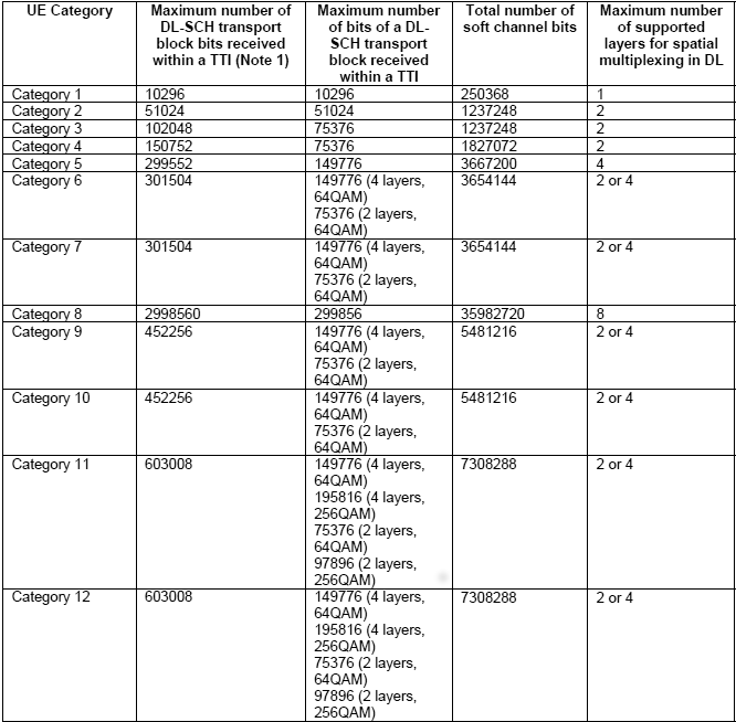
The following table depicts the UL physical layer parameters set by ue-Category.
Table 4.1-2: Uplink physical layer parameter values set by the field ue-Category
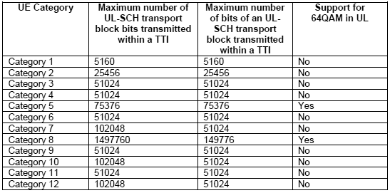
As can be seen in the above UE Capability Information message, the OnePlus3 phone declares to be a category 4 and category 6 device. LTE category 6 has only been added to the specification in release 10. As such, a category 6 device is required to report category 4 as well to be backward compatible with release 8 networks.
As a category 4 device, OnePlus3 is capable to support 150 Mbps in DL and 51 Mbps in UL at physical layer. DL throughput is achieved by using two layers spatial multiplexing and 64QAM modulation. As a category 6 device, OnePlus 3 device should achieve a max theoretical throughput of 301 Mbps in DL and 51 Mbps in DL.
The above ue-category tables only indicate the maximum theoretical throughput, but do not give any detail about the specific MIMO or CA configuration. As an example, a throughput of 301 Mbps in DL could be achieved either by combining two 20 MHZ carriers with each carrier supporting two layers spatial multiplexing or by using four layers spatial multiplexing in a single cell.
The most common case among commercial devices is to aggregate two carrier components of 20 MHZ each to achieve 301 Mbps in category 6. Looking back at OnePlus3 capabilities, we can see that the device is supporting carrier aggregation with two carrier components as seen in IE (Information Element) supportedBandCombination-r10. Its supported MIMO capability in DL in each carrier is two layers.
Starting from Release 12, a UE can indicate its DL category and UL category separately. The following table depicts the physical layer parameter values corresponding to ue-CategoryDL.
Table 4.1A-1 of 3GPP TS 36.306 v13.5: Downlink physical layer parameter values set by the field ue-CategoryDL.
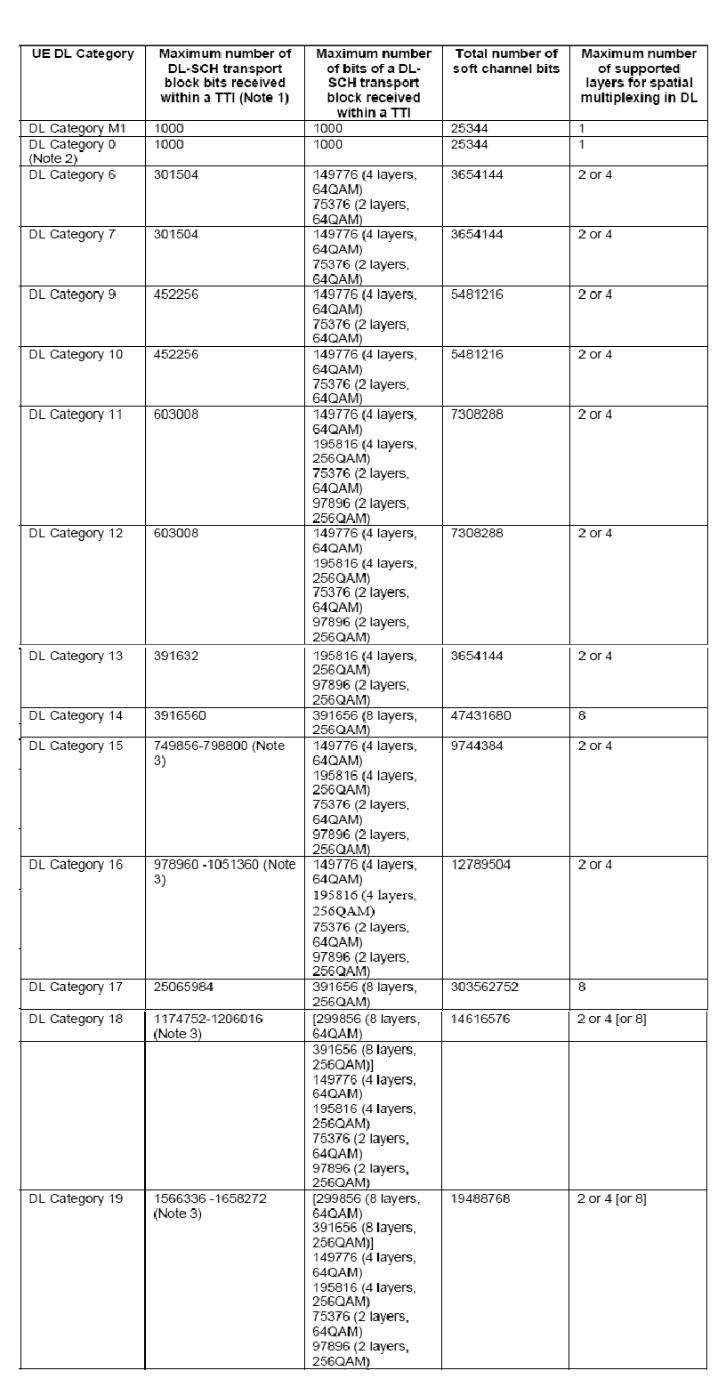
The following table depicts the physical layer parameter values corresponding to ue-CategoryUL.
Table 4.1A-2 of 3GPP TS 36.306 v13.5: Uplink physical layer parameter values set by the field ue-CategoryUL
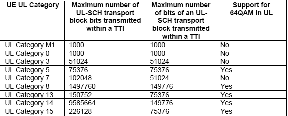
OnePlus3 device is also declaring to be category 13 in DL with 391 Mbps in DL. This category requires support of 256QAM in DL allowing transport blocks to carry up to 97896 bits. As can be seen in OnePlus3 UE Capability Information message, it declares to support 256QAM modulation on top of CA with two carriers and two layers spatial multiplexing in DL. Combining all these features, the OnePlus3 device is able to receive a maximum of 4 transport blocks with 256QAM modulation in a TTI, ie. two transport blocks per TTI per carrier. This will give a DL rate of 4 x 97896 x 1000 = 391 Mbps.
Oneplus3 device is also declaring to be category 5 in UL with 75 Mbps in UL. This category requires support of 64QAM in UL allowing transport blocks to carry up to 75376 bits.
Once the device maximum supported data rate in UL and DL is figured out, next step would be to configure CableFree network. This is discussed in the next section.
It would be worthy to note that these throughput numbers are theoretical. All DL/UL TTIs do not carry only user data, there are also a certain portion of overhead due to control part such as SIBs, signalling as well as user plane protocol headers. So real throughput you get will be less than the one listed in the above tables.
2.2 Network Configuration
The eNodeB configuration plays an important role to achieve best performance. Once the UE category is deduced, it is important to start eNodeB with the right configuration file. The following parameters are important to achieve maximum throughput.
- Cell bandwidth: The cell bandwidth has a direct impact on the maximum capacity of the cell. The higher the cell bandwidth, the higher will be the maximum throughput. In CableFree solution, the cell bandwidth is configured with the
n_rb_dlparameter giving the number of resource blocks. This parameter is available in eNodeB configuration file.- – Use
n_rb_dl = 6, 15, 25, 50, 75, 100for the bandwidths1.4, 3, 5, 10, 15, 20 MHz. - – To ease the bandwidth change, the enb.cfg configuration file has a define at the top named N_RB_DL that can be set to 6, 15, 25, 50, 75, 100.
- – In order to achieve the highest data rate within a cell, the cell bandwidth parameter should be set to 20 MHZ.
- – Use
- Transmission mode: In the downlink, LTE uses technologies such as MIMO to achieve high data rates. In LTE jargon, this is called transmission mode. It is configured with the
transmission_modeandtransmission_mode_optparameters in the eNodeB configuration file.- – For two layers spatial multiplexing,
transmission_modeparameter could be set to 3 or 4. - – Transmission modes 3 and 4 need rank indicator reporting for proper operation.
m_riparameter configures the periodicity of CQI/PMI reports and it should be set to a non-zero value. - – A typical example to enable 2×2 MIMO in DL is the file enb.cfg which is suitable for a cat 4 device. To use it in 2×2 DL MIMO 20MHz configuration, edit the file and change N_RB_DL to 100 and N_ANTENNA_DL to 2.
- – For two layers spatial multiplexing,
- Carrier aggregation: there are a lot of parameters to set in this case. A typical example is provided in file enb-2cc.cfg for a category 6 device. This file enables two cells with 5 MHZ bandwidth and in bands 3 and 7. To use it in 2×2 DL MIMO 20MHz configuration, edit the file and change N_RB_DL to 100 and N_ANTENNA_DL to 2.
- Number of resource blocks allocated to control: Indeed, not all the resource blocks within a cell could be allocated to user data:
- – In DL, typically some resource blocks should be dedicated to SIBs, PDCCH, etc. CableFree eNodeB allows you to specify the number of OFDM symbols for PDCCH. This is controlled with the
n_symb_cchparameter in eNodeB configuration file. A value of 0 means that eNodeB will automatically adjust the number of OFDM symbols. A value of 1 is the minimum that you can set for this parameter. The more UEs you have in your cell, the more OFDM symbols are required for PDCCH. So a value of 1 is useful for capacity testing to increase the number of resources blocks used for user data but in real life, this value should be set to 0 or > 1. - – in UL, some resource blocks are allocated to CQI reporting and PUCCH. This is controlled by
nRB-CQIandn1PUCCH-ANparameters in SIB2. Example below is taken from the default SIB2 and SIB3 configuration file sib2_3.asn used for a 20 MHZ cell in CableFree eNodeB. We can see that there are 20 resource blocks allocated for control in UL.pucch-ConfigCommon { deltaPUCCH-Shift ds2, nRB-CQI 8, nCS-AN 0, n1PUCCH-AN 12 },nRB-CQIandn1PUCCH-ANparameters could be decreased to 1 to gain a better UL throughput by editing the eNB configuration file and setting the parameterscqi_pucch_n_rbandn1_pucch_sr_countto 1. The more UEs you have in your cell, the more resources are required for PUCCH and CQI. So a value of 1 fornRB-CQIandn1PUCCH-ANis useful for capacity testing but in real life, this value should be set to > 1. You can as well check that the UL MCS is not limited by parameterpusch_max_mcsof eNodeB config file. If this is the case, you can comment the line.
- – In DL, typically some resource blocks should be dedicated to SIBs, PDCCH, etc. CableFree eNodeB allows you to specify the number of OFDM symbols for PDCCH. This is controlled with the
- Support of 256QAM in DL: It is configured with
dl_256qamparameter in eNodeB configuration file. If set to true, it allows 256QAM DL support for the release 12 UEs supporting this feature. - Support of 64QAM in UL: It is configured with
ul_64qamparameter in eNodeB configuration file. If set to true, it allows 64QAM UL support for the release 12 UEs supporting this feature. Please note that- If uplink 64QAM is not activated in the cell or the UE does not support it, eNodeB could allocate up to MCS 24 (even if MCS 21 to 24 are hardly usable on real network deployments as the coding rate starts to be quite high because you use the number of bits of a 64QAM MCS with a 16QAM modulation; the real last 16QAM MCS being MCS 20).
- If both cell and UE support uplink 64QAM, MCS could go up to MCS 28.
2.3 Number of users in the cell
An LTE cell has a certain capacity based on its configuration. As an example a 20 MHZ cell, could provide a theoretical maximum rate of 151 Mbps. If there is one single UE in the cell, then potentially the eNodeB could allocate all the cell resources to this single UE. If there are more than 1 UE in the cell, then the resources are shared among them and based on the scheduling algorithm used by the eNodeB, they can get a share of the cell capacity.
2.4 Signal Level
A perfect radio channel is required to achieve high throughput. If you are using antennas and there is some interference in the LTE band that you are testing or if you are not in Line of Sight, then you cannot achieve high rates.
We recommend the following setups in order to minimise the impact of interference in your testing:
- If you are using antennas for transmission and reception, you can use a shielded box to isolate your device from outside interference.
- You can RF cables to connect your UE to the eNodeB. In this case, please make sure to use attenuators and to tune the transmission gain at both sides in order not to saturate the signal. The parameters
tx_gainandrx_gainare configurable in eNodeB configuration file.
2.5 Application Level Configuration
iPerf tool is a commonly used network testing tool that can create TCP and UDP data streams and measure the end to end throughput. iPerf has a client and server functionality, and can measure the throughput between the two ends, either unidirectionally or bidirectionally. We recommend using iPerf for throughput tests as it is simple to use and install on a handset device.
In the following, we focus on throughput testing using iPerf.
2.5.1 iPerf Install on Network side
First, you need to install iPerf on the PC where your core network is running. This is the PC where you have installed LTEMME component.
Assuming you are using a Fedora distribution, you can use the following command:
sudo dnf install iperf
For Ubuntu, the following command can be used:
sudo apt-get install iperf
2.5.2 iPerf Install on UE side
You also need to install iPerf on your device under test. iPerf is available in Google Play for Android as shown below.

2.6 UDP/TCP configuration
UDP does not require any particular configuration neither on the operating system side nor on iPerf side.
For TCP, in order to achieve maximum throughput, the TCP advertised receiver window size must be equal to or greater than the BDP (Bandwidth Delay Product), which can be expressed as follows:
BDP = TCP Bandwidth * RTT
WhereTCP bandwidth is the portion of the radio bearer used to send TCP data. This is the data rate that you would like to achieve based on your UE category and cell configuration. RTT is the Round Trip Time between TCP end-points as seen by the TCP sender. In order to have an idea of the RTT of your link, you can ping your UE from the core network PC.
Please note that some operating systems have limitations on max TCP window size. You can of course tweak your phone if you are root. If you have an Android device, you can check the following parameters with root privilege:
- –
/proc/sys/net/ipv4/tcp_rmem: memory reserved for TCP receive buffers - –
/proc/sys/net/ipv4/tcp_wmem: memory reserved for TCP send buffers - –
/proc/sys/net/core/rmem_max: maximum receive window - –
/proc/sys/net/core/wmem_max: maximum send window
Parallel TCP connections could certainly help improve the TCP throughput if you can not change the above parameters in your device. With iPerf, you can use the -P option to start n parallel TCP connections.
2.7 Step by Step Throughput Testing
This section provides step by step instructions to test throughput using iPerf.
2.7.1 DL throughput test
To do a simple downlink test in MIMO CAT 4 at 150 Mbps in UDP, you can proceed as follows:
- Edit the configuration file enb.cfg and change N_RB_DL to 100 and N_ANTENNA_DL to 2
- Start your eNodeB using the configuration file enb.cfg
- run iPerf in server mode at the UE sideiperf -s -u -i 1
- Run iPerf in client mode on your core network PCiperf -c
-u -b 150M -i 1 -t 100 You can obtain the UE IP address, by typing uecommand on MME monitor.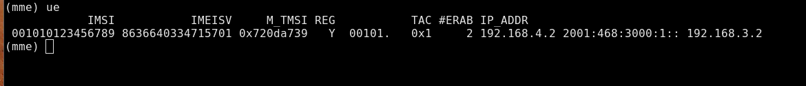
- Run the
tcommand in eNodeB screen to activate UE statistics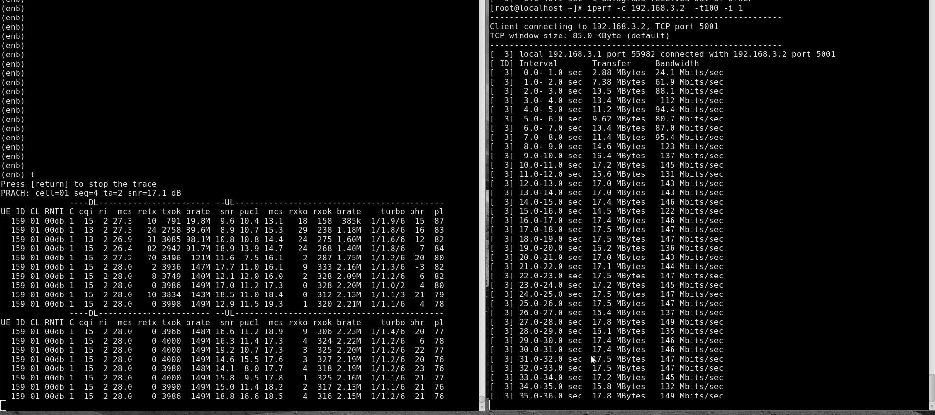 You can check
 bratefield in DL eNodeB stats for downlink throughput. You can as well check the iPerf application level throughput at the server window.
For a TCP connection, the steps are the same as above except for iPerf command. At UE side, you need to start iPerf in server mode as below:
iperf -s -i 1
The command to be used at core network PC side is:
iperf -c-i 1 -t 100
2.7.2 UL throughput test
To do a simple uplink test in MIMO CAT 4 at 50 Mbps in UDP, you can proceed as follows.
- Edit the configuration file enb.cfg and change N_RB_DL to 100
- Start your eNodeB using the configuration file mimo-2×2-20mhz.cfg
- Run the following command on your core network PCiperf -s -u -i 1
- run iPerf in client mode at the UE sideiperf -c
-u -b 50M -i 1 -t 100 Where the PDN Gateway IP addresscould be found by looking atgatewayparameter of thepdnobject inLTEMMEconfig file. In default configuration files, thegatewayparameter is not set for PDNs. In this case, the first IP of the subnet in IPv4 will be used as gateway IP address.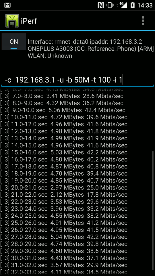
- Run the
tcommand in eNodeB screen to activate UE statistics.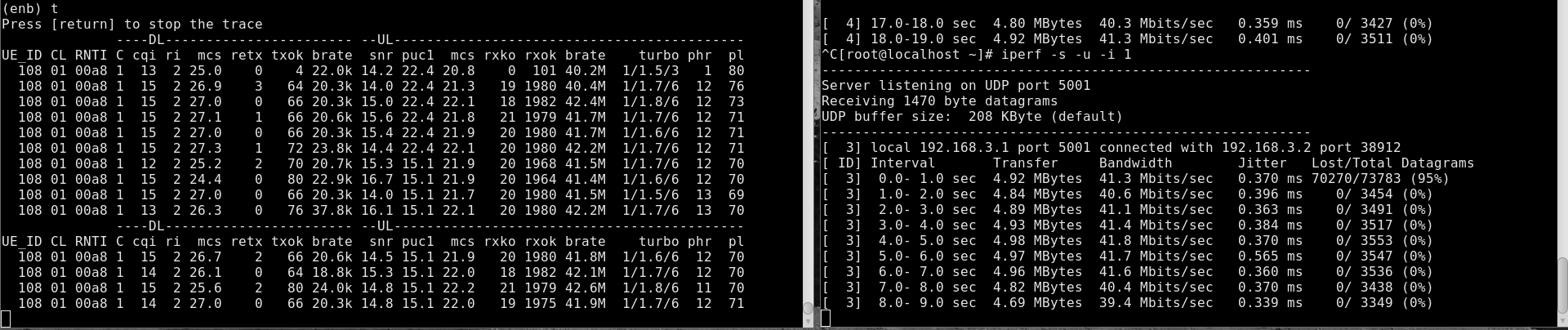
You can check brate field in UL eNodeB stats for uplink throughput. You can as well check the iPerf application level throughput at the server window.
For a TCP connection, the steps are the same as above except for iPerf command. At the core network PC side, you can type the following command:
iperf -s -i 1
At the UE side, the command to run is as below:
iperf -c-i 1 -t 100
2.7.3 Simultaneous UL/DL throughput test
For simultaneous UL/DL test, you need to either run two instances of iPerf, one in UL and one in DL as described above or to use the -d option. The below example is for bi-directional TCP test. On your core network PC, you can run
iperf -c-d -i 1 -t 100
On your device, you can run
iperf -s -i 1
Following is an example of UE statistics when running simultaneous UL/DL throughput test:
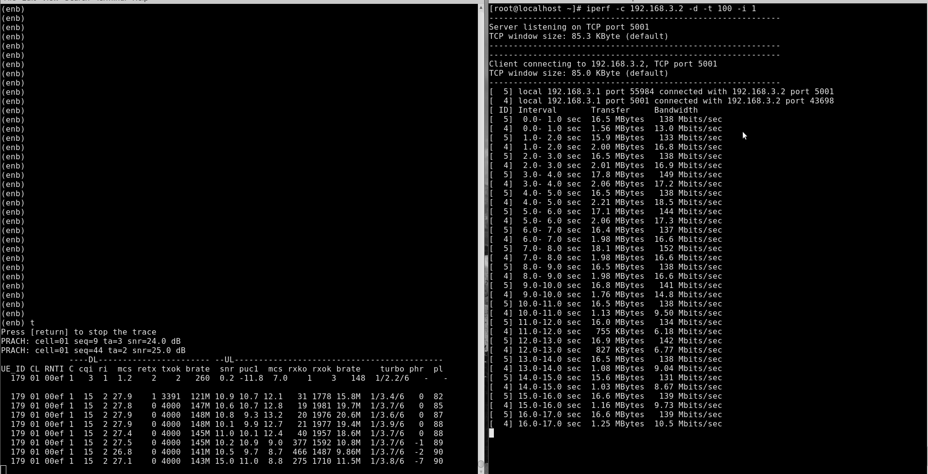
3 Logging
The CableFree eNodeB generates a log file at /tmp/enb0.log that could be used for for further analysis and debugging. Best is to activate physical layer debug traces by adding phy.level=debug to log_options field in your eNodeB config file.
4 Troubleshooting
Below are some of the most common issues encountered during testing with recommended actions to address each issue.
| Issue | Cause/Correction |
|---|---|
| Can not achieve maximum data rate in DL | Check eNodeB configuration to see if you have the right cell configuration: cell bandwidth, MIMO, etc. Activate eNodeB stats by typing t command in eNodeB screen. You should be seeing a CQI of 15 and an ri of 2 for MIMO. If this is not the case, check your signal level. Use UDP with iPerf to rule out any TCP or web server issue. |
| Can not achieve maximum data rate in UL | Check eNodeB configuration to see if you have the right cell configuration:- No pusch_max_mcs should be defined as otherwise you will be limiting the maximum UL data rate.- Check that the number of RBs reserved for control are reduced in SIB2. Activate eNodeB stats by typing t command in eNodeB screen. You should be seeing a high SNR and a non-negative power headroom phr. If this is not the case, check your signal level. Use UDP with iPerf to rule out any TCP or web server issue. Check the UL signal level by typing t spl command in eNodeB screen. The RX MAX reported by the command should be < 0, otherwise it means that the UE is transmitting too high. |
For Further Information
Please contact CableFree Support
support@cablefree.net
Main
CableFree: Wireless Excellence offer a wide range of support packages for all our partners/customers worldwide.
This can include
- Telephone support
- Teams/Google Meet
- Messaging (WhatsApp, Google Chat, etc)
- Remote Desktop
Please do contact our team who will be delighted to respond.
Please note that certain levels of support do require a support contact to be in place.
Best wishes,
CableFree Support Team
