Manual:Simple TE
Summary
This article shows how to simply create traffic engineering tunnels using both dynamic and static tunnel paths.It also shows how to steer traffic over the tunnel.
Network Layout
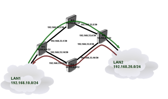
We will create a network consisting of four routers connected in diamond shape as illustrated in diagram below.
Each router is connected to neighboring router using /30 network and each of them have unique loopback address form 10.255.0.x network. Loopback addresses will be used as tunnel source and destination.
The goal is to interconnect two LAN segments (Lan1, Lan2) using TE tunnels in the way that:
- traffic in direction from LAN1 to LAN2 goes over path through R2
- traffic in direction from LAN2 to LAN1 goes over path through R4
Router Configurations
Connectivity between routers and Loopback addresses
R1
/system identity set name=R1

/interface bridge add name=Loopback

/ip address
add address=192.168.33.1/30 interface=ether1
add address=192.168.33.14/30 interface=ether2
add address=192.168.10.1/24 interface=ether3
add address=10.255.0.1/32 interface=Loopback
R2
/system identity set name=R2

/interface bridge add name=Loopback

/ip address
add address=192.168.33.2/30 interface=ether1
add address=192.168.33.5/30 interface=ether2
add address=10.255.0.2/32 interface=Loopback
R3
/system identity set name=R3

/interface bridge add name=Loopback

/ip address
add address=192.168.33.6/30 interface=ether1
add address=192.168.33.9/30 interface=ether2
add address=192.168.20.1/24 interface=ether3
add address=10.255.0.3/32 interface=Loopback
R4
/system identity set name=R4

/interface bridge add name=Loopback

/ip address
add address=192.168.33.10/30 interface=ether1
add address=192.168.33.13/30 interface=ether2
add address=10.255.0.4/32 interface=Loopback
Loopback address reachability and CSPF setup
In this setup we will use OSPF dynamic routing protocol to distribute routing information between routers. To successfully complete the setup we need loopback reachability information on every router.
CSPF will also be configured (extension of OSPF) to carry TE reservation information.
R1
/routing ospf instance
set default router-id=10.255.0.1 mpls-te-area=backbone mpls-te-router-id=Loopback

/routing ospf network
add network=192.168.33.0/24 area=backbone
add network=10.255.0.1/32 area=backbone
R2
/routing ospf instance
set default router-id=10.255.0.2 mpls-te-area=backbone mpls-te-router-id=Loopback

/routing ospf network
add network=192.168.33.0/24 area=backbone
add network=10.255.0.2/32 area=backbone
R3
/routing ospf instance
set default router-id=10.255.0.3 mpls-te-area=backbone mpls-te-router-id=Loopback

/routing ospf network
add network=192.168.33.0/24 area=backbone
add network=10.255.0.3/32 area=backbone
R4
/routing ospf instance
set default router-id=10.255.0.4 mpls-te-area=backbone mpls-te-router-id=Loopback

/routing ospf network
add network=192.168.33.0/24 area=backbone
add network=10.255.0.4/32 area=backbone
After OSPF is set up verify that we have correct routing information in routing table of each router:
[admin@R1] /ip route> print
Flags: X - disabled, A - active, D - dynamic,
C - connect, S - static, r - rip, b - bgp, o - ospf, m - mme,
B - blackhole, U - unreachable, P - prohibit
 #      DST-ADDRESS        PREF-SRC        GATEWAY            DISTANCE
 0 ADS  0.0.0.0/0                          10.5.101.1                1
 1 ADC  10.255.0.1/32      10.255.0.1      lo                        0
 2 ADo  10.255.0.2/32                      192.168.33.2            110
 3 ADo  10.255.0.3/32                      192.168.33.2            110
                                           192.168.33.13
 4 ADo  10.255.0.4/32                      192.168.33.13           110
 5 ADC  192.168.10.0/30    192.168.10.1    ether3                    0
 6 ADC  192.168.33.0/30    192.168.33.1    ether1                    0
 7 ADo  192.168.33.4/30                    192.168.33.2            110
 8 ADo  192.168.33.8/30                    192.168.33.13           110
 9 ADC  192.168.33.12/30   192.168.33.14   ether2                    0
Setting Resource Reservation
Next step is to set up TE resource for every interface on which we might want to run TE tunnel.
Configuration on all the routers are the same:
/mpls traffic-eng interface
add interface=ether1 bandwidth=10Mbps
add interface=ether2 bandwidth=10Mbps
Since we are not using real bandwidth limitation on the tunnels in this example, bandwidth parameter is only used for administrative purposes and can be any value (it does not represent how much bandwidth will actually flow through the interface).
TE tunnel setup
Since our primary goal is to strictly forward traffic over specific path we will use static path configuration as primary, and dynamic (CSPF) as secondary path if primary fails.
R1
/mpls traffic-eng tunnel-path
add name=dyn use-cspf=yes
add name=tun-first-link use-cspf=no \
   hops=192.168.33.2:strict,192.168.33.5:strict,192.168.33.6:strict

/interface traffic-eng
add bandwidth=5Mbps name=TE-to-R3 to-address=10.255.0.3 primary-path=tun-first-link \
   secondary-paths=dyn record-route=yes from-address=10.255.0.1
R3
/mpls traffic-eng tunnel-path
add name=dyn use-cspf=yes
add name=tun-second-link use-cspf=no \
   hops=192.168.33.10:strict,192.168.33.13:strict,192.168.33.14:strict

/interface traffic-eng
add bandwidth=5Mbps name=TE-to-R1 to-address=10.255.0.1 primary-path=tun-second-link \
   secondary-paths=dyn record-route=yes from-address=10.255.0.3
Verify that TE tunnels are working
[admin@R1] /interface traffic-eng> monitor 0
             tunnel-id: 14
    primary-path-state: established
          primary-path: tun-first-link
  secondary-path-state: not-necessary
           active-path: tun-first-link
          active-lspid: 1
          active-label: 39
        explicit-route: S:192.168.33.2/32,S:192.168.33.5/32,S:192.168.33.6/32
    reserved-bandwidth: 5.0Mbps
Notice that running router will show assigned MPLS lables, whole tunnel path and reserved bandwidth. Reserved resources also can be monitored on each router:
[admin@R1] /mpls traffic-eng> path-state print
Flags: L - locally-originated, E - egress, F - forwarding, P - sending-path,
R - sending-resv
 #      SRC                  DST                  BANDWIDTH OUT.. OUT-NEXT-HOP
 0 LFP  10.255.0.1:1         10.255.0.3:15          5.0Mbps eth.. 192.168.33.2
 1  E R 10.255.0.3:1         10.255.0.1:8           5.0Mbps
[admin@R1] /mpls traffic-eng> resv-state print
Flags: E - egress, A - active, N - non-output, S - shared
 #    SRC                  DST                  BANDWIDTH LABEL            INT...
 0 AS 10.255.0.1:1         10.255.0.3:15          5.0Mbps 41               ether1
[admin@R1] /mpls traffic-eng>
[admin@R1] /mpls traffic-eng> interface print
Flags: X - disabled, I - invalid
 #   INTERFACE                                  BANDWIDTH  TE-METRIC REMAINING-BW
 0   ether1                                        10Mbps          1      5.0Mbps
 1   ether2                                        10Mbps          1     10.0Mbp
Notice that remaining bandwidth on interface decreased. It means that if multiple tunnels are created and whole bandwidth on that particular interface is used, then tunnel will try to look for different path.
Note: TE tunnels are unidirectional, meaning that tunnel may be running in one direction but fail in another direction if whole resources are reserved
Route Traffic over TE
To route LAN traffic over TE tunnel we will assign address 10.99.99.1/30 and 10.99.99.2/30 to each tunnel end.
R1
/ip address add address=10.99.99.1/30 interface=TE-to-R3

/ip route add dst-address=192.168.20.0/24 gateway=10.99.99.2
R3
/ip address add address=10.99.99.2/30 interface=TE-to-R1

/ip route add dst-address=192.168.10.0/24 gateway=10.99.99.1
To verify if traffic is actually going over TE tunnel and is label switched we can run traceroute:
[admin@R1] /ip address> /tool traceroute  10.99.99.1
 # ADDRESS                                 RT1   RT2   RT3   STATUS
 1 192.168.33.2                            2ms   1ms   1ms   <MPLS:L=41,E=0>
 2 10.99.99.1                              3ms   1ms   1ms
As you can see traceroute recorded MPLS label in the path.
Congratulations our setup works.
Failover Testing
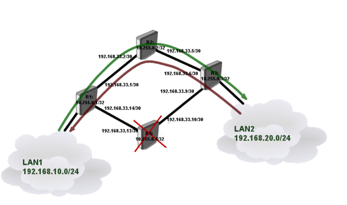
Lets consider that router R4 went down, and whole traffic needs to be switched over R2.
Traffic engineering does not switch paths automatically. If we use dynamic path then path relies on OSPF routing information and is recalculated whenever one of the link fails. In case of static primary paths as in our case, we need to re-optimize the tunnel. It can be done in two ways:
- manually - which is not what we need
- automatically - at specific interval
To set up path re-optimization we need to specify interval.
R1
/interface trafic-eng set TE-to-R3 reoptimize-interval=5s
R3
/interface trafic-eng set TE-to-R1 reoptimize-interval=5s
After a while tunnel will switch paths do secondary
[admin@R3] /interface traffic-eng> monitor 0
             tunnel-id: 10
    primary-path-state: trying-to-establish
          primary-path: tun-second-link
  secondary-path-state: established
        secondary-path: dyn
           active-path: dyn
          active-lspid: 3
          active-label: 45
        explicit-route: S:192.168.33.5/32,S:192.168.33.2/32,S:192.168.33.1/32
    reserved-bandwidth: 5.0Mbps
By default tunnel will try to switch back to primary path every minute. This setting can be changed with primary-retry-interval parameter.
Note: Switching from primary to secondary path may not be as fast as expected. It depends on OSPF dead timeouts, routing table updates and timeout settings in TE tunnel configuration.
Extended Tunnel for VoIP
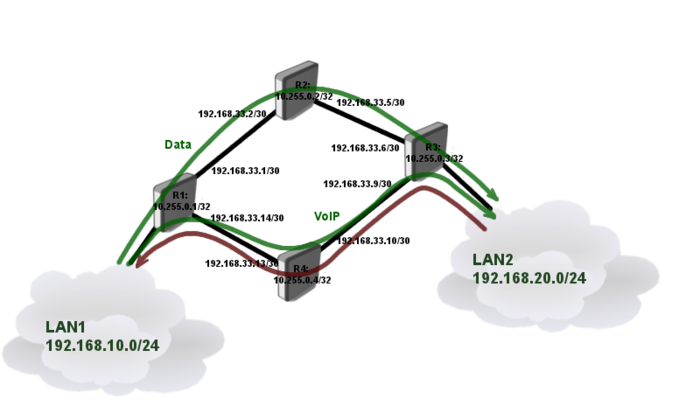
Lets consider that in network that we made previously, path through R4 has lower latency which is good for VoIP traffic. Since VOIP server is on LAN2 we will create another TE tunnel from R1 to R3 explicitly for VoIP traffic.
Assuming that previous configuration is up and running, we will start with path definition for VOIP tunnel.
R1
/mpls traffic-eng tunnel-path
add name=tun-second-link use-cspf=no \
   hops=192.168.33.13:strict,192.168.33.10:strict,192.168.33.9:strict

/interface traffic-eng
add name=TE-to-R3-VOIP to-address=10.255.0.3 bandwidth=5Mbps record-route=yes \
   primary-path=tun-second-link secondary-paths=dyn reoptimize-interval=5s
Verify that tunnel is up and running
[admin@R1] /interface traffic-eng> monitor TE-to-R3-VOIP
             tunnel-id: 19
    primary-path-state: established
          primary-path: tun-second-link
  secondary-path-state: not-necessary
           active-path: tun-second-link
          active-lspid: 1
          active-label: 20
        explicit-route: S:192.168.33.13/32,S:192.168.33.10/32,S:192.168.33.9/32
        recorded-route: 192.168.33.10[20],192.168.33.9[0]
    reserved-bandwidth: 5.0Mbps
Notice that we are doing configuration only in one direction, since traffic coming back form the server will use the same tunnel as regular data.
Now it is time to set up routing.
Let's consider that VoIP server's IP address is 192.168.20.250. We will also need to set up IP addresses on tunnel ends.
R1
/ip address add address=10.100.100.1/30 interface=TE-to-R3-VOIP

/ip route add dst-address=192.168.20.250/32 gateway=10.100.100.2
R3
/ip address add address=10.100.100.2/30 interface=TE-to-R1
See More
[ Top | Back to Content ]


