Carrier Aggregation in LTE-A (LTE Advanced)
Carrier Aggregation is a key technology in LTE Advanced (LTE-A) to enable higher capacities on mobile networks. carrier aggregation mainstream, with global proliferation, which benefits the entire mobile ecosystem: Operators, App developers, and OEMs – by delivering higher data rates, improved capacity, and the ability to use spectrum fragments.
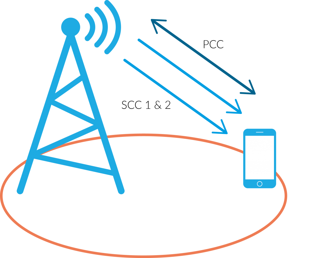
A simple diagram explaining Carrier Aggregation is here below, showing two channels being aggregated together to provide double the data capacity to the user device:
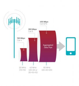
Delivering successively higher data rates
Carrier aggregation in LTE offers successively higher peak data rates as well as better broadband experience across the coverage area.
The date rates scale with the amount of spectrum allowing 3GPP Rel 10 to support up to 5 carriers with up to 100 MHz of spectrum and commercial solutions to support up to 3 carriers with peak data rates up to 450 Mbps (Cat 5).
LTE Advanced with Carrier Aggregation – User Equipment (UE) capacity increases
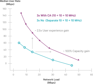
Higher capacity for bursty applications
Increased data rates of carrier aggregation can be traded off to get higher capacity for bursty applications, such as web browsing, streaming, social media apps and others, meaning operators can choose a higher capacity for the same user experience, better user experience for the same capacity, or both.
CA benefits the whole LTE industry
Users gain next-level user experience:
– Higher data rates with lower latency across the network
– Faster downloads of pictures, files, webpages, higher quality videos, etc.
Operators can make the most of all spectrum assets:
– Higher network capacity
– Opportunity to offer new apps/services which use higher data rates and capacity
App Developers can transform mobile experiences:
– Substantially richer user experience
– New immersive multimedia, such as 4K
– Fully utilize multimedia and connectivity of modern smartphones
Manufacturers show technology leadership and differentiation:
– Lead with early adoption
– Offer tiered devices based on speed and device capability
– Expand carrier aggregation proliferation to address global markets
LTE Advanced offers considerably higher data rates than even the initial releases of LTE. While the spectrum usage efficiency has been improved, this alone cannot provide the required data rates that are being headlined for 4G LTE Advanced.
To achieve these very high data rates it is necessary to increase the transmission bandwidths over those that can be supported by a single carrier or channel. The method being proposed is termed carrier aggregation, CA, or sometimes channel aggregation. Using LTE Advanced carrier aggregation, it is possible to utilise more than one carrier and in this way increase the overall transmission bandwidth.
These channels or carriers may be in contiguous elements of the spectrum, or they may be in different bands.
Spectrum availability is a key issue for 4G LTE. In many areas only small bands are available, often as small as 10 MHz. As a result carrier aggregation over more than one band is contained within the specification, although it does present some technical challenges.
Carrier aggregation is supported by both formats of LTE, namely the FDD and TDD variants. This ensures that both FDD LTE and TDD LTE are able to meet the high data throughput requirements placed upon them.
LTE carrier aggregation basics
The target figures for data throughput in the downlink is 1 Gbps for 4G LTE Advanced. Even with the improvements in spectral efficiency it is not possible to provide the required headline data throughput rates within the maximum 20 MHz channel. The only way to achieve the higher data rates is to increase the overall bandwidth used. IMT Advanced sets the upper limit at 100 MHz, but with an expectation of 40 MHz being used for minimum performance. For the future it is possible the top limit of 100 MHz could be extended.
It is well understood that spectrum is a valuable commodity, and it takes time to re-assign it from one use to another in view – the cost of forcing users to move is huge as new equipment needs to be bought. Accordingly as sections of the spectrum fall out of use, they can be re-assigned. This leads to significant levels of fragmentation.
To an LTE terminal, each component carrier appears as an LTE carrier, while an LTE-Advanced terminal can exploit the total aggregated bandwidth.
RF aspects of carrier aggregation
There are a number of ways in which LTE carriers can be aggregated:
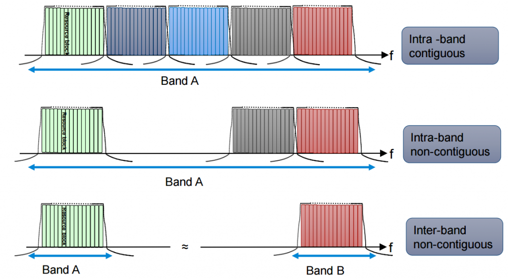
- Intra-band: This form of carrier aggregation uses a single band. There are two main formats for this type of carrier aggregation:
- Contiguous: The Intra-band contiguous carrier aggregation is the easiest form of LTE carrier aggregation to implement. Here the carriers are adjacent to each other.
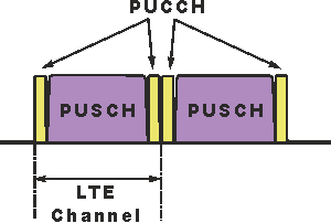
Contiguous aggregation of two uplink component carriers
-
The aggregated channel can be considered by the terminal as a single enlarged channel from the RF viewpoint. In this instance, only one transceiver is required within the terminal or UE, whereas more are required where the channels are not adjacent. However as the RF bandwidth increases it is necessary to ensure that the UE in particular is able to operate over such a wide bandwidth without a reduction in performance. Although the performance requirements are the same for the base station, the space, power consumption, and cost requirements are considerably less stringent, allowing greater flexibility in the design. Additionally for the base station, multi-carrier operation, even if non-aggregated, is already a requirement in many instances, requiring little or no change to the RF elements of the design. Software upgrades would naturally be required to cater for the additional capability.
- Non-contiguous: Non-contiguous intra-band carrier aggregation is somewhat more complicated than the instance where adjacent carriers are used. No longer can the multi-carrier signal be treated as a single signal and therefore two transceivers are required. This adds significant complexity, particularly to the UE where space, power and cost are prime considerations.
- Contiguous: The Intra-band contiguous carrier aggregation is the easiest form of LTE carrier aggregation to implement. Here the carriers are adjacent to each other.
- Inter-band non-contiguous: This form of carrier aggregation uses different bands. It will be of particular use because of the fragmentation of bands – some of which are only 10 MHz wide. For the UE it requires the use of multiple transceivers within the single item, with the usual impact on cost, performance and power. In addition to this there are also additional complexities resulting from the requirements to reduce intermodulation and cross modulation from the two transceivers
The current standards allow for up to five 20 MHz carriers to be aggregated, although in practice two or three is likely to be the practical limit. These aggregated carriers can be transmitted in parallel to or from the same terminal, thereby enabling a much higher throughput to be obtained.
Carrier aggregation bandwidths
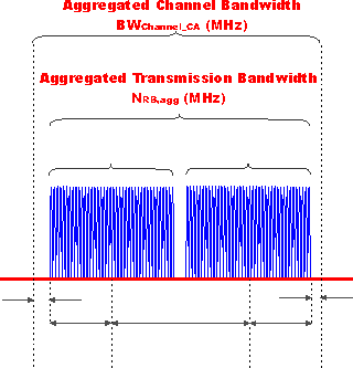
When aggregating carriers for an LTE signal, there are several definitions required for the bandwidth of the combined channels. As there as several bandwidths that need to be described, it is necessary to define them to reduce confusion.
LTE carrier aggregation bandwidth classes
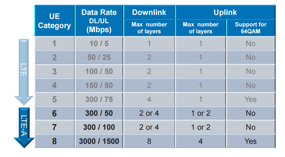
There is a total of six different carrier aggregation, CA bandwidth classes which are being defined.
| CARRIER AGGREGATION BANDWIDTH CLASS |
AGGREGATED TRANSMISSION BW CONFIGURATION |
NUMBER OF COMPONENT CARRIERS |
|---|---|---|
|
A
|
≤100
|
1
|
|
B
|
≤100
|
2
|
|
C
|
100 – 200
|
2
|
NB: classes D, E, & F are in the study phase.
LTE aggregated carriers
When carriers are aggregated, each carrier is referred to as a component carrier. There are two categories:
- Primary component carrier: This is the main carrier in any group. There will be a primary downlink carrier and an associated uplink primary component carrier.
- Secondary component carrier: There may be one or more secondary component carriers.
There is no definition of which carrier should be used as a primary component carrier – different terminals may use different carriers. The configuration of the primary component carrier is terminal specific and will be determined according to the loading on the various carriers as well as other relevant parameters.
In addition to this the association between the downlink primary carrier and the corresponding uplink primary component carrier is cell specific. Again there are no definitions of how this must be organised. The information is signalled to the terminal of user equipment as part of the overall signalling between the terminal and the base station.
Carrier aggregation cross carrier scheduling
When LTE carrier aggregation is used, it is necessary to be able to schedule the data across the carriers and to inform the terminal of the DCI rates for the different component carriers. This information may be implicit, or it may be explicit dependent upon whether cross carrier scheduling is used.
Enabling of the cross carrier scheduling is achieved individually via the RRC signalling on a per component carrier basis or a per terminal basis.
When no cross carrier scheduling is arranged, the downlink scheduling assignments achieved on a per carrier basis, i.e. they are valid for the component carrier on which they were transmitted.
For the uplink, an association is created between one downlink component carrier and an uplink component carrier. In this way when uplink grants are sent the terminal or UE will know to which uplink component carrier they apply.
Where cross carrier scheduling is active, the PDSCH on the downlink or the PUSCH on the uplink is transmitted on an associate component carrier other than the PDCCH, the carrier indicator in the PDCCH provides the information about the component carrier used for the PDSCH or PUSCH.
It is necessary to be able to indicate to which component carrier in any aggregation scheme a grant relates. To facilitate this, component carriers are numbered. The primary component carrier is numbered zero, for all instances, and the different secondary component carriers are assigned a unique number through the UE specific RRC signalling. This means that even if the terminal or user equipment and the base station, eNodeB may have different understandings of the component carrier numbering during reconfiguration, transmissions on the primary component carrier can be scheduled.
Carrier Aggregation Summary
CableFree LTE-A Base Stations include full support for CA with latest Release 12 LTE-A software. CableFree LTE hardware and software is scalable and upgradable for future needs and increases in coverage and capacity. Deploying a CableFree LTE network will ensure latest technology and capacity for your network.
For Further Information
Please Contact Us for more information on our exciting range of solutions using LTE technology

You must be logged in to post a comment.