Different frame structures are used in LTE for FDD and TDD modes.
Here we present information, overview, or tutorial about the LTE frame and subframe structure including LTE Type 1 and LTE Type 2 frames.
In order that the 3G LTE system can maintain synchronisation and the system is able to manage the different types of information that need to be carried between the base-station or eNodeB and the User Equipment, UE, 3G LTE system has a defined LTE frame and subframe structure for the E-UTRA or Evolved UMTS Terrestrial Radio Access, i.e. the air interface for 3G LTE.
The frame structures for LTE differ between the Time Division Duplex, TDD and the Frequency Division Duplex, FDD modes as there are different requirements on segregating the transmitted data.
There are two types of LTE frame structure:
Type 1: used for the LTE FDD mode systems.
Type 2: used for the LTE TDD systems.
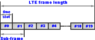
Type 1 LTE Frame Structure
The basic type 1 LTE frame has an overall length of 10 ms. This is then divided into a total of 20 individual slots. LTE Subframes then consist of two slots – in other words there are ten LTE subframes within a frame.

Type 2 LTE Frame Structure
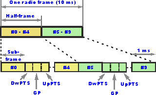
The frame structure for the type 2 frames used on LTE TDD is somewhat different. The 10 ms frame comprises two half frames, each 5 ms long. The LTE half-frames are further split into five subframes, each 1ms long.

(shown for 5ms switch point periodicity).
The subframes may be divided into standard subframes of special subframes. The special subframes consist of three fields;
- DwPTS – Downlink Pilot Time Slot
- GP – Guard Period
- UpPTS – Uplink Pilot Time Stot.
These three fields are also used within TD-SCDMA and they have been carried over into LTE TDD (TD-LTE) and thereby help the upgrade path. The fields are individually configurable in terms of length, although the total length of all three together must be 1ms.
LTE TDD / TD-LTE subframe allocations
One of the advantages of using LTE TDD is that it is possible to dynamically change the up and downlink balance and characteristics to meet the load conditions. In order that this can be achieved in an ordered fashion, a number of standard configurations have been set within the LTE standards.
A total of seven up / downlink configurations have been set, and these use either 5 ms or 10 ms switch periodicities. In the case of the 5ms switch point periodicity, a special subframe exists in both half frames. In the case of the 10 ms periodicity, the special subframe exists in the first half frame only. It can be seen from the table below that the subframes 0 and 5 as well as DwPTS are always reserved for the downlink. It can also be seen that UpPTS and the subframe immediately following the special subframe are always reserved for the uplink transmission.
| UPLINK-DOWNLINK CONFIGURATION | DOWNLINK TO UPLINK SWITCH PERIODICITY | SUBFRAME NUMBER | |||||||||
|---|---|---|---|---|---|---|---|---|---|---|---|
| 0 | 1 | 2 | 3 | 4 | 5 | 6 | 7 | 8 | 9 | ||
| 0 | 5 ms | D | S | U | U | U | D | S | U | U | U |
| 1 | 5 ms | D | S | U | U | D | D | S | U | U | D |
| 2 | 5 ms | D | S | U | D | D | D | S | U | D | D |
| 3 | 10 ms | D | S | U | U | U | D | D | D | D | D |
| 4 | 10 ms | D | S | U | U | D | D | D | D | D | D |
| 5 | 10 ms | D | S | U | D | D | D | D | D | D | D |
| 6 | 5 ms | D | S | U | U | U | D | S | U | U | D |
Where:
D is a subframe for downlink transmission
S is a “special” subframe used for a guard time
U is a subframe for uplink transmission
For Further Information
Please contact us with any questions on CableFree Wireless Technology and 4G/LTE

You must be logged in to post a comment.