Decibel Power Measurement (dB) FAQs
Summary

Wireless link designers – just as with Fibre Optics – use Decibels to calculate power transmission losses and link budgets.
The Decibel explained
The Decibel is a sub-unit of a larger unit called the bel. As originally used, the bel represented the power ratio of 10 to 1 between the strength or intensity of two sounds, and was named after Alexander Graham Bell.
Bels represents a logarithmic relationship since the (common log) logarithm of 100 (to the base 10) is 2 (corresponding to 2 bels), the logarithm of 1000 to the base 10 is 3 (corresponding to 3 bels), etc. The exact relationship is given by the formula Bels = log(P2/P1) , where P2/P1 represents the power ratio.
Since the bel is a rather large unit, it is not useful for precise measurements. Usually a smaller unit, the Decibel or dB, is used. 10 decibels make one bel. A 10:1 power ratio – 1 bel – = +-10 dB; a 100:1 ratio = 2 bels = 20 dB. Thus the formula becomes
Decibels (dB) = 10 log(P2/P1)
With the constant almost always included in modern terminology and power referred to as a “ten log” function.
In this equation, P1 is usually the reference power. If P2 is less than P1, the ratio is less then 1.0 and the resultant (exponent) value is negative. For example, if P2 is one-tenth of P1, we have:
dB = 10 log(0.1/1) = -10 dB.
The term decibel does not in itself indicate power, but rather is a ratio or comparison between two power values.
It is often desirable to express power levels in decibels by using a fixed power as a reference. The most common references in the world of electronics are the milliwatt (mW) and the watt. The abbreviation dBm indicates dB referenced to 1.0 milliwatt. One milliwatt output power is then zero dBm. Thus P1 in equations [1] or [2] becomes 1.0 mW.
Logarithmic Power Measurements for Wireless Links

The logarithmic characteristic of the dB makes it very convenient for expressing power ratios. Consider an amplifier with an output of 100 watts when the input is 0.1 watts (100 milliwatts);
it has an amplification factor of
P2/P1 = 100/0.1 = 1000
or a gain of:
10 log(P2/P1) = 10 log(100/0.1) = 30 dB.
(notice the 3 in 30 dB corresponds to the number of zeros in the power ratio)
Conversely, a ratio of less than 1.0 is a loss, a negative gain, and will be expressed as a negative dB value. For instance, if 10 watts of power is fed into a cable but only 8.5 watts are measured at the output, the signal has been decreased by a factor of
8.5/10 = 0.85
or
10 log(0.85) = -0.7 dB.
An attenuator, cable or optical path that reduces its input power by factor of 0.001 has an attenuation of 30 dB or a gain of -30 dB.
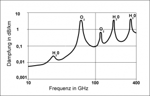
The dB is very useful when describing signal loss due to radiation through the atmosphere. It is much easier to work with a loss of 137 dB rather than the equivalent factor of 2 x 10-14 mW – a number that cannot be easily manipulated.
Better still, instead of multiplying gain or loss factors as percentages, by using dB measurement we can add them as positive or negative dB values. Link budgets are therefore much easier to calculate.
dB SOLUTIONS WITHOUT A CALCULATOR
If the power in question is not a multiple of ten, then some estimation is required. The following tabulation lists some approximations, which can be helpful if memorized.
dB RULES OF THUMB:
Double the power: +3 dB
Halve the power: -3 dB
Ten times the power: +10 dB
One tenth the power: -10 dB
100 times the power: +20 dB
1/100 the power : -20 dB
dB AS ABSOLUTE UNITS = dBm
Power in absolute units can be expressed by using 1 milliwatt as the reference power in the denominator of the equation for dB. We then call it dBm. We can then build a table such as this:
10.0 mW = +10 dBm
2.0 mW = +3 dBm
1.0 mW = 0 dBm
0.5 mW = -3 dBm
0.1 mW = -10 dBm
The “m” in dBm references the value to an absolute value of 1 mW of power which is a standard reference throughout the fiber optic and wireless industries.
For Further Information
Please Contact Us
You must be logged in to post a comment.