Free Space Optics: FSO Laser Guide
A Guide to Laser History

Lasers are one of the most significant inventions of the 20th century – they can be found in many modern products, from CD players to fibre-optic networks. The word laser is actually an acronym for Light Amplification by Stimulated Emission of Radiation. Although stimulated emission was first predicted by Albert Einstein near the beginning of the 20th century, the first working laser was not demonstrated until 1960 when Theodore Maiman did so using a ruby. Maiman’s laser was predated by the maser – another acronym, this time for Microwave Amplification by Stimulated Emission of Radiation. A maser is very similar to a laser except the photons generated by a maser are of a longer wavelength outside the visible and/or infrared spectrum.
How a Laser Works
A laser generates light, either visible or infrared, through a process known as stimulated emission. To understand stimulated emission, understanding two basic concepts is necessary. The first is absorption which occurs when an atom absorbs energy or photons. The second is emission which occurs when an atom emits photons. Emission occurs when an atom is in an excited or high energy state and returns to a stable or ground state – when this occurs naturally it is called spontaneous emission because no outside trigger is required. Stimulated emission occurs when an already excited atom is bombarded by yet another photon causing it to release that photon along with the photon which previously excited it. Photons are particles, or more properly quanta, of light and a light beam is made up of what can be thought of as a stream of photons.
A basic laser uses a mirrored chamber or cavity to reflect light waves so they reinforce each other. An excitable substance – gas, liquid, or solid like the original ruby laser – is contained within the cavity and determines the wavelength of the resulting laser beam. Through a process called pumping, energy is introduced to the cavity exciting the atoms within and causing a population inversion. A population inversion is when there are more excited atoms than grounded atoms which then leads to stimulated emission. The released photons oscillate back and forth between the mirrors of the cavity, building energy and causing other atoms to release more photons. One of the mirrors allows some of the released photons to escape the cavity resulting in a laser beam emitting from one end of the cavity.
Laser Communications History
Some first experiments in laser communications were performed by NASA and the Air Force. One of the early experiments actually utilized Morse code – a technician simply chopped the beam with his hand to send a coded message to the remote receiver. The first patents for laser communications were filed in the 1960’s. From this time through the 80’s various defence related organizations experimented with laser communications. Essentially all of the engineering of today’s laser communications systems was done over the past 40 years or so, mostly for defence applications. By addressing the principal engineering challenges, this aerospace/defence activity established a strong foundation upon which today’s commercial optical wireless systems are based. Ground to aircraft, ground to satellite, satellite to satellite, even satellite to submarine applications were all experimented with.
Laser safety and Classifications
Laser communications systems can be designed to be eye-safe, which means that they pose no danger to people who might happen to encounter the communications beam. Laser eye safety is classified by the International Electrotechnical Commission (IEC), which is the international standards body for all fields of electrotechnology. While the IEC is an advisory agency, its guidelines are adopted by the regulatory agencies in most of the world’s countries. A laser transmitter that is completely safe when viewed by the unaided eye is designated IEC Class 1M. In the U.S., laser eye safety is controlled by the Center for Devices and Radiological Health (CDRH), a division of the Food and Drug Administration (FDA). Currently, the CDRH is in the process of adopting the safety classifications of the IEC.
Note, however, that the eyesafe limits vary with wavelength. The optical wireless hardware currently on the market can be classified into two broad categories – systems that operate at a wavelength near 800 nm and those that operate near 1550 nm. Laser beams at 800 nm are near-infrared and therefore invisible, yet like visible wavelengths, the light passes through the cornea and lens and is focused onto a tiny spot on the retina. This is schematically illustrated in the diagram, which applies for visible and near-infrared wavelengths in the range of 400 to 1400 nm. The collimated light beam entering the eye in this retinal-hazard wavelength region is concentrated by a factor of 100,000 times when it strikes the retina. Thus, at 800 nm the retina could be permanently damaged by some commercially available optical-wireless products before the victim is aware that hazardous illumination has occurred. In contrast, the lower diagram schematically shows that laser beams at wavelengths greater than 1400 nm are absorbed by the cornea and lens, and do not focus onto the retina. Because of these biophysical properties of the eye, wavelengths > 1400 nm are allowed approximately 50 times greater intensities than wavelengths near 800 nm. This fact can be exploited by specifying a wavelength in the 1550 nm range, where the factor of fifty additional laser power allows the system to propagate over longer distances and/or support higher data rates.
Historically, most developers of such systems have employed wavelengths in the near-visible infrared spectral region (~ 780 nm to ~ 850 nm), principally because of the availability of efficient and reliable direct semiconductor diode-based sources at those wavelengths, and, for the 780 nm devices, the cost advantages of utilizing the same wavelength as is used in CD recorders. While cost is obviously an important factor in the wavelength trade, one must also consider several additional constraints, most notably the need not to exceed eye-safe limits on transmitted intensities under conditions of high data-rate transmissions through heavy atmospheric attenuation (due to fog, for example). Other important trade criteria include overall performance, and the potential for system growth and scalability. When all of these factors are considered, it becomes clear that a more judicious approach is to employ wavelengths near 1550 nm, the same wavelength range used in commercial fibre-optic communications networks.
Terrestrial Laser Communications Challenges
Fog

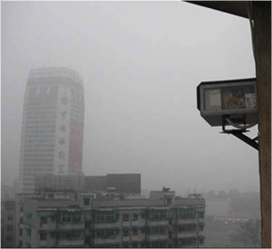
Fog substantially attenuates visible radiation, and it has a similar affect on the near-infrared wavelengths that are employed in laser communications. Similar to the case of rain attenuation with RF wireless, fog attenuation is not a “show-stopper” for optical wireless, because the optical link can be engineered such that, for a large fraction of the time, an acceptable power will be received even in the presence of heavy fog. Laser communication systems can be enhanced to yield even greater availabilities by combining them with RF systems.
Physical Obstructions
Laser communications systems that employ multiple, spatially diverse transmitters and large receive optics will eliminate interference concerns from objects such as birds.
Pointing Stability
Pointing stability in commercial laser communications systems is achieved by one of two methods. The simpler, less costly method is to widen the beam divergence so that if either end of the link moves the receiver will still be within the beam. The second method is to employ a beam tracking system. While more costly, such systems allow for a tighter beam to be transmitted allowing for higher security and longer distance transmissions.
Scintillation
Performance of many laser communications systems is adversely affected by scintillation on bright sunny days. Through a large aperture receiver, widely spaced transmitters, finely tuned receive filtering, and automatic gain control, downtime due to scintillation can be avoided.
For Further Information
For more information on this FSO Guide please Contact Us
You must be logged in to post a comment.