Introduction to Microwave

Microwave is a line-of-sight wireless communication technology that uses high frequency beams of radio waves to provide high speed wireless connections that can send and receive voice, video, and data information.
Microwave links are extensively utilised for point-to-point communications due to their short wavelengths, which enable conveniently-sized antennas to focus signals into narrow beams aimed directly at receiving antennas. This precision allows multiple microwave systems to operate on the same frequencies without interference, unlike lower-frequency radio waves. Additionally, the high frequency of microwaves provides a very large information-carrying capacity, with the microwave band offering a bandwidth 30 times greater than the entire radio spectrum below it.
Microwave radio transmission is widely used in terrestrial point-to-point communication systems, satellite communications, and deep-space radio communications. Other applications of the microwave band include radars, radio navigation, sensor systems, and radio astronomy.
Frequencies in the higher radio spectrum, between 30 GHz and 100 GHz, are termed “millimeter waves” due to their wavelengths, which range from 10 mm to 3 mm. These waves are strongly attenuated by the Earth’s atmosphere and its particles, particularly in wet conditions. At around 60 GHz, molecular oxygen in the atmosphere further attenuates these waves. The technology required for millimeter wave systems is more complex and harder to produce compared to microwave band technologies, resulting in higher costs for millimeter wave radios.
History of Microwave Communication
In 1865, James Clerk Maxwell predicted the existence of electromagnetic waves, including microwaves, through his “Maxwell’s equations”. Heinrich Hertz confirmed this in 1888 by generating and detecting ultra-high-frequency microwaves, validating Maxwell’s theory but seeing no practical use. Subsequent work by pioneers like Nikola Tesla, Guglielmo Marconi, and others led to the development of wireless communications using microwaves.

In 1931, a US-French consortium tested a microwave relay link across the English Channel, transmitting telephony, telegraph, and facsimile data over 1.7 GHz beams,. However, it couldn’t compete with cheaper undersea cables, so a planned commercial system was never built.
By the 1950s, AT&T’s Long Lines microwave relay system, tested in 1946 (TDX prototype) and operational between New York and Boston by 1947, became the backbone for most US long-distance telephone traffic and intercontinental TV signals.
Modern Commercial Microwave Links

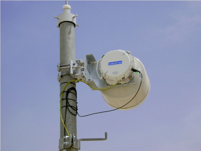
Microwave links use radio waves in the microwave frequency range to send video, audio or data between two points, ranging from a few metres to several kilometres apart. Examples of commercial microwave links from CableFree may be see here. Modern microwave links can achieve data rates up to 400Mbps in a 56MHz channel using 256QAM modulation and IP header compression. The operational range of these links depends on antenna size (gain), frequency, and link capacity, with a clear line of sight being essential, especially when accounting for the Earth’s curvature.

Television broadcasters frequently use microwave links to transmit programmes nationally or from outside broadcasts to studios. Mobile units are often camera mounted and enable free movement without trailing cables. These are commonly used with Steadicam systems on sports field sidelines.
Planning of microwave links
CableFree Microwave links have to be planned considering the following parameters:
- Required distance (km/ miles) and capacity (Mbps)
- Desired Availability target (%) for the link
- Availability of Clear Line of Sight (LOS) between end nodes
- Towers or masts if required to achieve clear LOS
- Allowed frequency bands specific to region/ country
- Environmental constraints, including rain fade
- Cost of licenses for required frequency bands
Microwave Frequency Bands

Microwave signals are often divided into three categories:
ultra high frequency (UHF) (0.3-3 GHz);
super high frequency (SHF) (3-30 GHz); and
extremely high frequency (EHF) (30-300 GHz).
In addition, microwave frequency bands are designated by specific letters. The designations by the Radio Society of Great Britain are given below.
L band: 1 to 2 GHz
S band: 2 to 4 GHz
C band: 4 to 8 GHz
X band: 8 to 12 GHz
Ku band: 12 to 18 GHz
K band: 18 to 26.5 GHz
Ka band: 26.5 to 40 GHz
Q band: 30 to 50 GHz
U band: 40 to 60 GHz
V band: 50 to 75 GHz
E band: 60 to 90 GHz
W band: 75 to 110 GHz
F band: 90 to 140 GHz
D band: 110 to 170 GHz
The term “P band” is sometimes used for ultra high frequencies below the L-band. For other definitions, see Letter Designations of Microwave Bands.
Lower microwave frequencies are used for longer links, and regions with higher rain fade. Conversely, higher frequencies are used for shorter links and regions with lower rain fade.
Rain Fade on Microwave Links

Rain fade describes the absorption of microwave radio frequency (RF) signals by atmospheric precipitation such as rain, snow or ice, with significant impact at frequencies above 11 GHz. It also involves signal degradation due to electromagnetic interference from a storm front’s leading edge.
Rain fade can occur at either the uplink or downlink location, and it doesn’t need to be raining at the site for the signal to be affected. The transmitted signal may pass through precipitation far away, particularly with low-angle satellite dishes. Additionally, 5 to 20 percent of signal loss may result from rain, snow, or ice accumulating on the antenna’s reflector, radome, or feed horn. Rain fade affects not only satellite links but also terrestrial point-to-point microwave links.
To mitigate the impact of rain fade, various strategies are used, including site diversity, uplink power control, variable rate encoding, using larger (higher-gain) receiving antennas than normally required, and applying hydrophobic coatings to antenna surfaces.
Diversity in Microwave Links
Diversity schemes are used to improve signal reliability by transmitting data across multiple channels with differing characteristics. These techniques help counter fading, co-channel interference and error bursts, using the fact that different channels experience varying levels of fading and interference. Signals can be transmitted and/or received in multiple versions and combined at the receiver, or redundant forward error correction codes can be used to send parts of the message over different channels. Diversity techniques often utilise multipath propagation to achieve a diversity gain.
The following classes of diversity schemes are typical in Terrestrial Microwave Links:
- Unprotected (1+0): A single set of microwave equipment with no diversity or backup, offering no protection against failures.
- Hot Standby (HSB, 1+1): Two sets of microwave equipment share the same antenna and frequency, with one active and the other in standby mode (receiver active, transmitter muted). If the active unit fails, the standby unit activates.
- Frequency diversity (N+1): The signal is transmitted over multiple frequency channels, including one protection channel to automatically replace a faded channel, mitigating frequency-selective fading.
- Space diversity: The signal travels through multiple propagation paths, achieved via multiple wires or multiple transmitter and/or receiving antennas (transmit/ reception diversity).
- Polarisation diversity: Signals are transmitted and received using antennas with different polarisations, combined at the receiver using a diversity combining technique.
Diverse Path Resilient Failover
In terrestrial point-to-point microwave systems (11 GHz to 80 GHz), a parallel backup link can be installed alongside a high-bandwidth primary link prone to rain fade. For example, a primary link such as an 80 GHz, 1 Gbit/s full-duplex microwave bridge with 99.9% availability may be down for 10+ hours annually due to heavy rain. A secondary, lower-bandwidth link, such as a 5.8 GHz, 100 Mbit/s bridge, can be installed in parallel, with routers enabling automatic failover to the backup link during rain fade. This setup allows high-frequency links (23 GHz+) to serve distant locations with greater reliability, achieving up to 99.99% uptime annually.
Automatic Coding and Modulation (ACM)

Link adaptation, or Adaptive Coding and Modulation (ACM), is a technique that dynamically adjusts modulation, coding and other parameters based on real-time radio link conditions such as path loss, interference, and signal strength. For instance, EDGE uses a rate adaptation algorithm to modify the modulation and coding scheme (MCS) to optimise data rate and transmission robustness based on channel quality. ACM aims to improve link efficiency by maximising network capacity over existing infrastructure while minimising sensitivity to environmental interferences.
With Adaptive Modulation, systems adjust modulation dynamically to maintain connectivity during adverse conditions like rain fade, ensuring maximum throughput in clear conditions and gradual degradation otherwise. This prevents microwave designers having to design for worst-case scenarios to avoid outages.
Benefits of ACM include:
- Longer link distances
- Using smaller antennas (saving mast space and meeting residential requirements)
- Improved link reliability (higher availability)
Automatic Transmit Power Control (ATPC)
CableFree Microwave links feature ATPC which automatically increases the transmit power during “fade” conditions such as heavy rainfall. ATPC can be used separately to ACM or together to maximise link uptime, stability and availability. When the “fade” conditions (rainfall) are over, the ATPC system reduces the transmit power again. This reduces the stress on the microwave power amplifiers, which reduces power consumption, heat generation and increases expected lifetime (MTBF).
Uses of microwave links
- Backbone links and “Last Mile” Communication for cellular network operators
- Backbone links for Internet Service Providers (ISPs) and Wireless ISPs (WISPs)
- Corporate Networks for Building to Building and campus sites
- Telecommunications, in linking remote and regional telephone exchanges to larger (main) exchanges without the need for copper/optical fibre lines.
- Broadcast Television with HD-SDI and SMPTE standards
Enterprise
Because of the scalability and flexibility of Microwave technology, Microwave products can be deployed in many enterprise applications including building-to-building connectivity, disaster recovery, network redundancy and temporary connectivity for applications such as data, voice and data, video services, medical imaging, CAD and engineering services, and fixed-line carrier bypass.
Mobile Carrier Backhaul

Microwave Links are a valuable tool in Mobile Carrier Backhaul: Microwave technology can be deployed to provide traditional PDH 16xE1/T1, STM-1 and STM-4, and Modern IP Gigabit Ethernet backhaul connectivity and Greenfield mobile networks. Microwave is far quicker to install and lower Total Cost of Ownership for Cellular Network Operators compared to deploying or leasing fibre optic networks.
Low Latency Networks
CableFree Low Latency versions of Microwave links use Low Latency Technology, with minimal delay between packets being transmitted and received at the other end, except the Line of Sight propagation delay. The Speed of Microwave propagation through the air is approximately 40% higher than through fibre optics, giving customers an immediate 40% reduction in latency compared to fibre optics. In addition, fibre optic installations are almost never in a straight line. With realities of building layout, street ducts and requirement to use existing telecom infrastructure, the fibre run can be 100% longer than the direct Line of Sight path between two end points. Hence CableFree Low Latency Microwave products are popular in Low Latency Applications such as High Frequency Trading and other uses.
For Further Information
For further information on the range of CableFree wireless networking products:
Please Contact Us
